P341/EN O/B11 Operation Guide
CHAPTER 2 Installation
Page 6/10 MiCOM P341
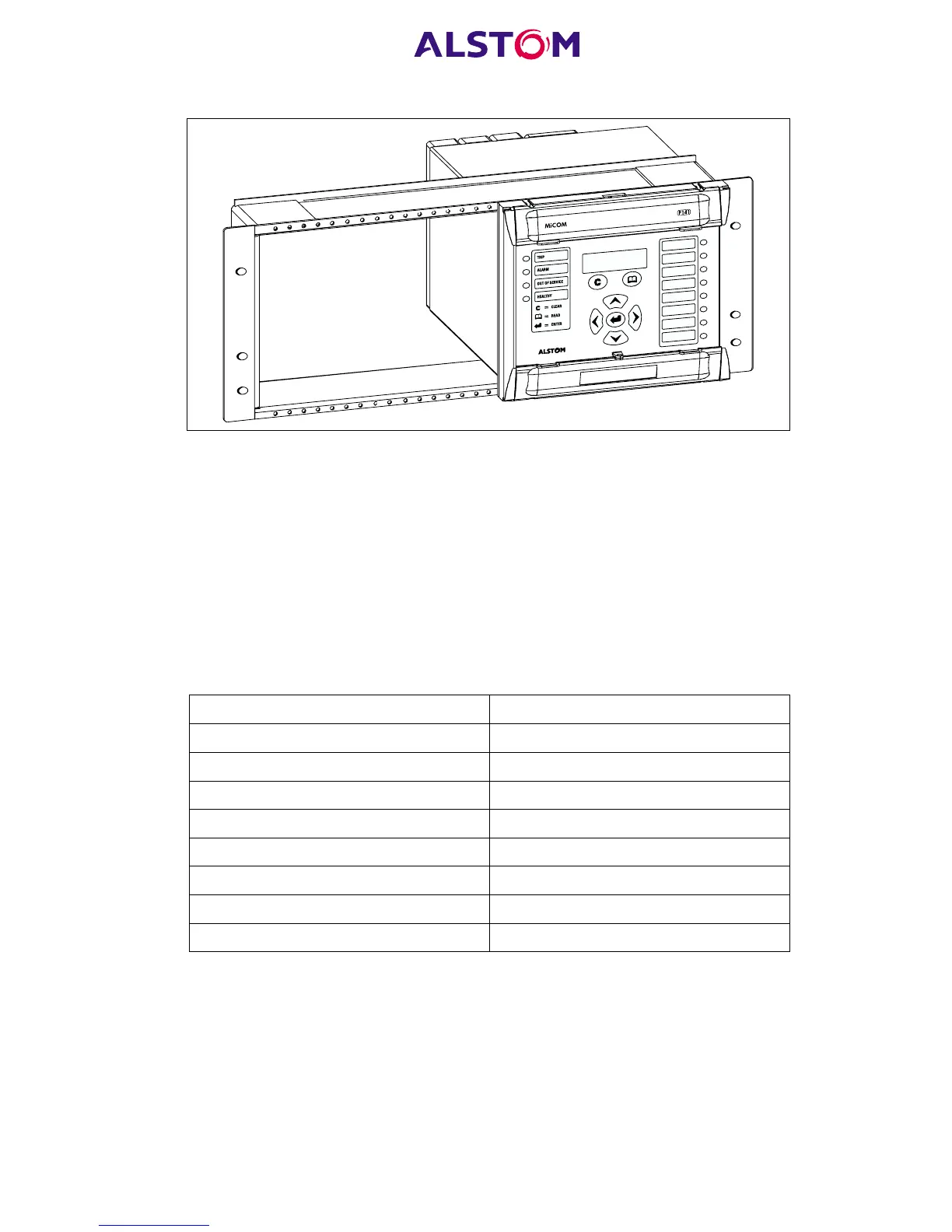
Figure 2: Rack mounting of relays
Relays can be mechanically grouped into single tier (4U) or multi-tier arrangements
by means of the rack frame. This enables schemes using products from the MiCOM
and MiDOS product ranges to be pre-wired together prior to mounting.
Where the case size summation is less than 80TE on any tier, or space is to be left for
installation of future relays, blanking plates may be used. These plates can also be
used to mount ancillary components. Table 1 shows the sizes that can be ordered.
Note: Blanking plates are only available in black.
Further details on mounting MiDOS relays can be found in publication R7012,
“MiDOS Parts Catalogue and Assembly Instructions”.
Case Size Summation Blanking Plate Part Number
5TE GJ2028 001
10TE GJ2028 002
15TE GJ2028 003
20TE GJ2028 004
25TE GJ2028 005
30TE GJ2028 006
35TE GJ2028 007
40TE GJ2028 008
Table 1: Blanking plates
Where an external dc supply (e.g. station battery) greater than 54V is being used to
energise the optically isolated inputs of a relay, resistor boxes mounted external to the
relay are available to reduce the voltage across the inputs. Table 2 details the two
versions of external resistor box that are available.
Note: Each box contains 8 resistors. Therefore one external resistor
box is required for each input board in the relay being used (i.e.
one external resistor box for each 8 optically isolated inputs).
 Loading...


