P341/EN O/B11 Operation Guide
CHAPTER 3 Commissioning and
Page 16/80 Maintenance
MiCOM P341
4.2.8 Current inputs
This test verifies that the accuracy of current measurement is within the acceptable
tolerances.
All relays will leave the factory set for operation at a system frequency of 50Hz. If
operation at 60Hz is required then this must be set in cell [0009: SYSTEM DATA,
Frequency].
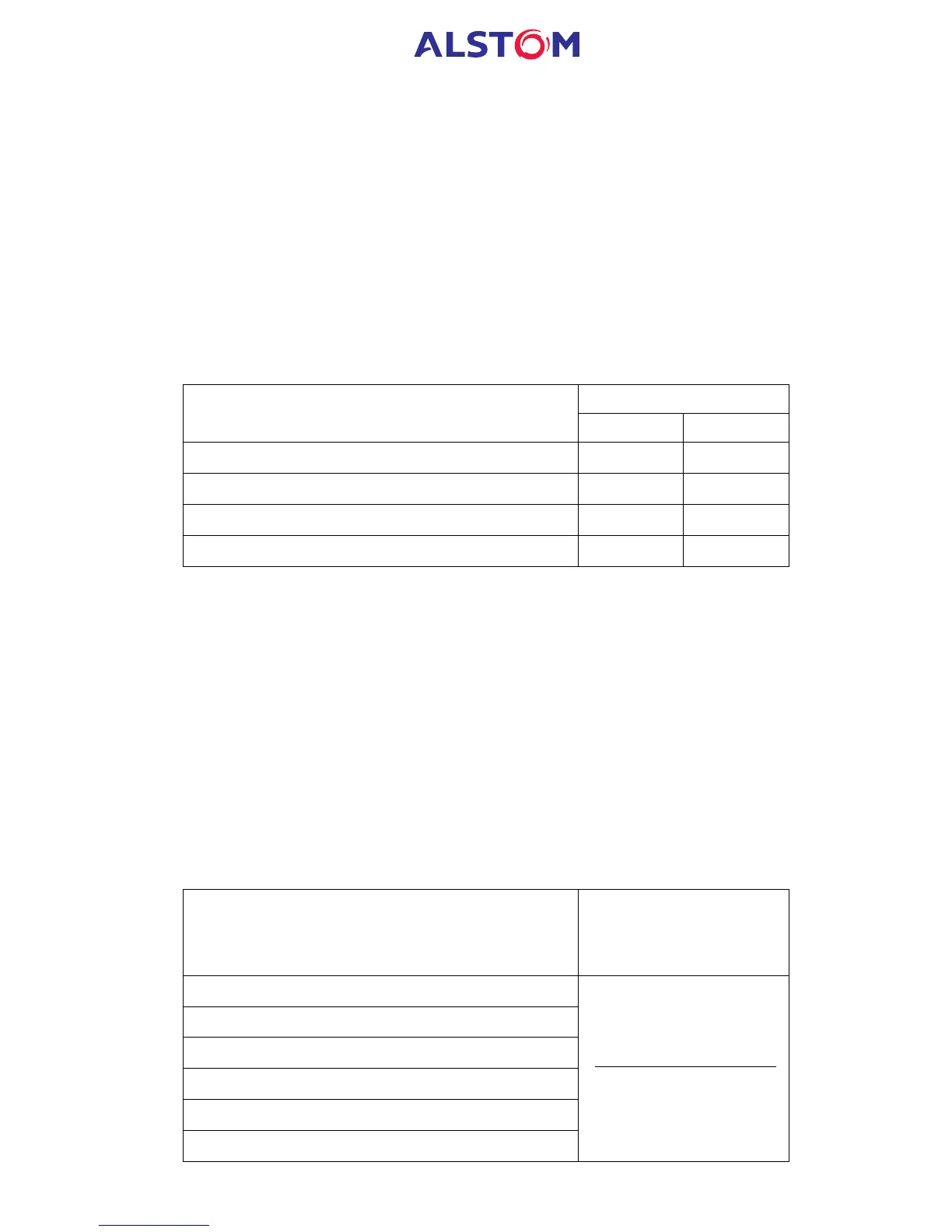
Apply current equal to the line current transformer secondary winding rating to each
current transformer input of the corresponding rating in turn, checking its magnitude
using a multimeter. Refer to Table 9 for the corresponding reading in the relay’s
MEASUREMENTS 1 or MEASUREMENTS 3 columns, as appropriate, and record the
value displayed.
Apply Current To
Menu Cell
1A Line CT 5A Line CT
[0201: MEASUREMENTS 1, fA Magnitude]
C3 – C2 C1 – C2
[0203: MEASUREMENTS 1, fB Magnitude]
C6 – C5 C4 – C5
[0205: MEASUREMENTS 1, fC Magnitude]
C9 – C8 C7 – C8
[020B: MEASUREMENTS 1, fSEF Magnitude]
C15 – C14 C13 – C14
Table 9: Current input terminals
The measured current values displayed on the relay LCD or a portable PC connected
to the front communication port will either be in primary or secondary Amperes. If
cell [0D02: MEASURE’T SETUP, Local Values] is set to ‘Primary’, the values displayed
should be equal to the applied current multiplied by the corresponding current
transformer ratio set in the ‘CT and VT RATIOS’ menu column (see Table 10). If cell
[0D02: MEASURE’T SETUP, Local Values] is set to ‘Secondary’, the value displayed
should be equal to the applied current.
Note: If a PC connected to the relay via the rear communications port is being
used to display the measured current, the process will be similar. However,
the setting of cell [0D03: MEASURE’T SETUP, Remote Values] will determine
whether the displayed values are in primary or secondary Amperes.
The measurement accuracy of the relay is ±1%. However, an additional allowance
must be made for the accuracy of the test equipment being used.
Menu Cell
Corresponding CT Ratio
(in ‘VT and CT RATIO
column (0A) of menu)
[0201: MEASUREMENTS 1, fA Magnitude]
[0203: MEASUREMENTS 1, fB Magnitude]
[0205: MEASUREMENTS 1, fC Magnitude]
[0401: MEASUREMENTS 3, fA-2 Magnitude]
[0403: MEASUREMENTS 3, fB-2 Magnitude]
[0405: MEASUREMENTS 3, fC-2 Magnitude]
[0A07: Phase CT Primary]
[0A08: Phase CT Sec'y]
 Loading...


