Operation Guide P341/EN O/B11
Commissioning and CHAPTER 3
Maintenance Page 21/80
MiCOM P341
If it has been necessary to disconnect any of the external wiring from the relay in
order to perform any of the foregoing tests, it should be ensured that all connections
are replaced in accordance with the relevant external connection or scheme diagram.
6.1 Voltage connections
Using a multimeter measure the voltage transformer secondary voltages to ensure
they are correctly rated. Check that the system phase rotation is correct using a
phase rotation meter.
Compare the values of the secondary phase voltages with the relay’s measured
values, which can be found in the MEASUREMENTS 1 menu column.
If cell [0D02: MEASURE’T SETUP, Local Values] is set to ‘Secondary’, the values
displayed on the relay LCD or a portable PC connected to the front RS232
communication port should be equal to the applied secondary voltage. The values
should be within 1% of the applied secondary voltages. However, an additional
allowance must be made for the accuracy of the test equipment being used.
If cell [0D02: MEASURE’T SETUP, Local Values] is set to ‘Primary’, the values
displayed should be equal to the applied secondary voltage multiplied the
corresponding voltage transformer ratio set in the ‘CT & VT RATIOS’ menu column
(see Table 14). Again the values should be within 1% of the expected value, plus an
additional allowance for the accuracy of the test equipment being used.
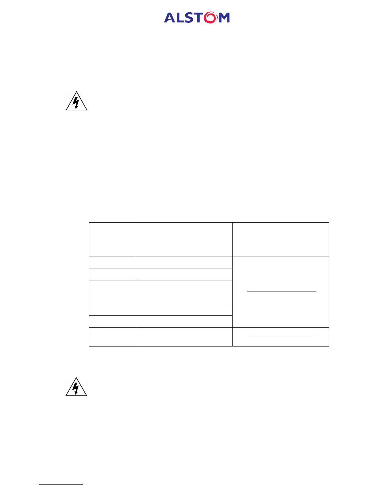
Voltage
Cell in MEASUREMENTS 1
Column (02)
Corresponding VT Ratio
(in ‘VT and CT RATIO
column (0A) of menu)
V
AB
[0214: VAB Magnitude]
V
BC
[0216: VBC Magnitude]
V
CA
[0218: VCA Magnitude]
V
AN
[021A: VAN Magnitude]
V
BN
[021C: VBN Magnitude]
V
CN
[021E: VCN Magnitude]
[0A01: Main VT Primary]
[0A02: Main VT Sec'y)]
V
N
[0220: VN Measured Mag]
[0A03: C/S VT Primary]
[0A04: C/S VT Sec'y]
Table 14: Measured voltages and VT ratio settings
6.2 Current connections
Measure the current transformer secondary values for each input using a multimeter
connected in series with corresponding relay current input.
Check that the current transformer polarities are correct by measuring the phase
angle between the current and voltage, either against a phase meter already installed
on site and known to be correct or by determining the direction of power flow by
contacting the system control centre.
Ensure the current flowing in the neutral circuit of the current transformers is
negligible.
 Loading...


