12 Tensor
4.5 Initial operation
4.5.1 Electrical connection
Hazardous voltage: Possible stroke!
• The initial operation must be carried out only by experts!
• De-energize the actuator before opening.
• Observe the appropriate regulations during electrical installation and initial
operation.
Connect the actuator as follows (wiring diagram see chapter 4.5.2):
• Connect the ground wire of the electric supply to the appropriate protective earth terminal.
• Always refer to the wiring diagram located inside the actuator.
Check prior to initial switch on:
• Is the actuator undamaged on the outside?
• Is the mechanical connection correct?
• Has the electrical connection been made regularly?
• Check if current type, voltage and frequency match with the motor data (see nameplate on cover and inside the actuator).
• Insert suitable cable glands for the connection line.
• Observe the wiring diagram inside the cover.
• Use separate (shielded) wires for low voltages.
• Set up limit switches prior to initial operation.
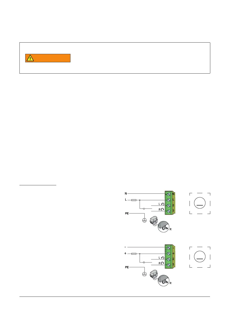
4.5.2 Wiring diagram
Connection 85...265 V AC
N Neutral conductor
L Phase / Supply 85 ... 265 V AC
2 Control connection > left-turning
3 Control connection > right-turning
Connect the ground wire to the housing.
–/+ Connection 24…48 V DC
2 Control connection > left-turning
3 Control connection > right-turning
Version 24/48 V DC
M
M