21Tensor
7. Operation of actuators with microprocessor controller I-ACT (PMR)
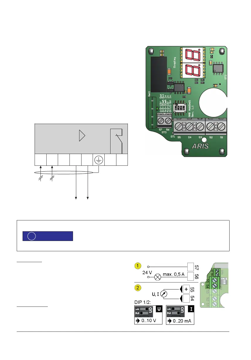
7.1 Wiring diagram and pin con guration
57/56 Message output, potential free opener, max. 200 V,
max. 0.5 A, max. 10 W
55 Actual value output, +
54 Actual value, ground
53 + 5 V supply
52 Set value input +
51 Set value input, ground
All drives are preset at the factory. When you change the DIP switch, the instructions given
here are to be observed!
The function of the inputs and outputs at pin 51 to 55 is set by DIP switches, see section 7.2.
The message output is used for operational monitoring.
Message output
The message output (1) Pin 56/57 works as potential free
activated opener. The capacity of the contact is
max. 200 V supply
max. 0.5 A
max. 10 W
Actual value output
The output (2) at pin 54 / signal terminal 55 is supplying voltage or
current depending on the DIP switch setting.
The output is galvanically isolated from the other ports.
0(4)–20 mA (DC)
optional 0–10 V (DC)
51 52 54
55
–
+ – +
0–20 mA (DC)
optional 0–10 V (DC)
I-ACT
53 5756
Störmelde-
ausgang
(potentialfrei)
1
1
2
2
3
3
4
4
5
5
6
6
A A
B B
C C
D D
Name
Ind.
Bemerkungen / Lieferant
MA
KBD AddOn 03
31.03.2015
Zeichnungsnummer
Freigabe
Gezeichnet
Gepr
üft
KBD AddOn 03.iam
Ersatz für
Mat.-Zustand / Behandlung
Index
Änderung
Datum
Rohmasse
Ersetzt durch
Projektion
3D-Modell
Massstab
Material
Allgemeintoleranzen
ISO 2768-mk
Auto
Manu
Right
Left
Menu
Error
Service
fault message
output
(potential free)