22 Tensor
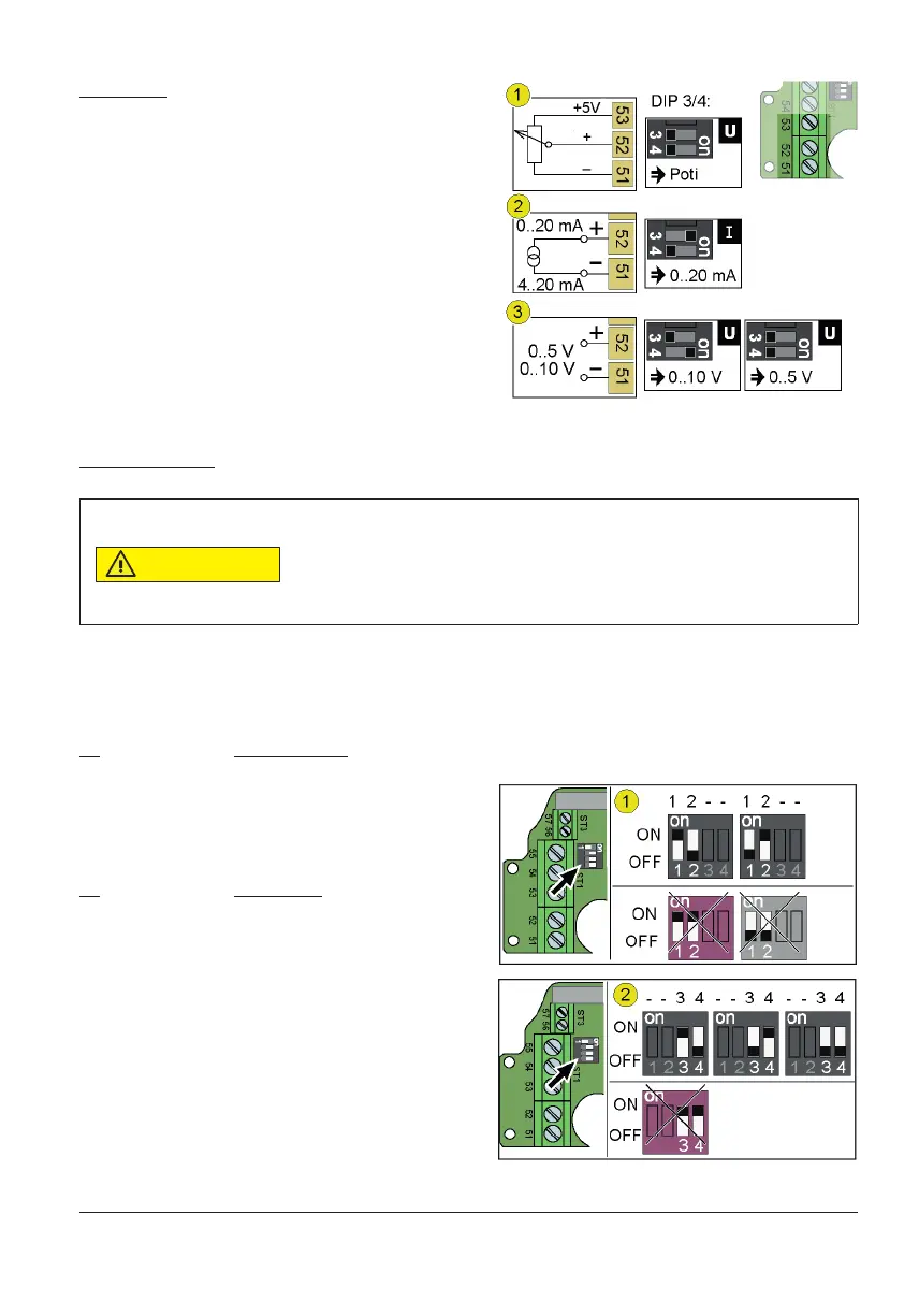
Set value input
Via pin 51/52 the controller receives a set value. When connecting a
potentiometer (1) pin 53 supplies the encoder with the supply voltage.
Via the DIP switches 3 and 4, the controller receives the information for
use of input:
− Set value via poti (1)
− Set value as current (2)
− Set value as voltage (3)
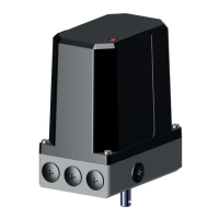
7.2 Con gure controller connection
To operate a drive control, the DIP switches must be con gured correct-
ly and the ports on the controller I-ACT (PMR) connected appropriately.
Setting up DIP switches
Component damage by short-circuit.
The DIP switches 1-2 and 3-4 switch to the same outputs. If the DIP switches 1 and 2 or the
DIP switches 3 and 4 are ON during operation, a short circuit can destroy components.
− Do not set DIP 1 and 2 to ON at once
− Do not set DIP 3 and 4 to ON at once
Via DIP 1-2 (1) the actual value output is con gured. With DIP 3-4 (2) con gure the set-point input.
Cut off supply voltage, set up DIP switches:
DIP Actual value output
1 ON / 2 OFF 0...10 V
1 OFF / 2 ON 0...20 mA
DIP 1 and DIP 2 to OFF creates an unde ned condition.
DIP Set value input
3 ON / 4 OFF 0...20 mA
3 OFF / 4 ON 0...10 V
3 OFF / 4 OFF 0...5 V / Poti operation