EasyManuals Logo

Aritech 2X Series User Manual

Aritech 2X Series
140 pages
To Next Page IconTo Next Page
To Previous Page IconTo Previous Page
Page #11 background imageLoading...
Page #11 background image
Chapter 1: Introduction
2X Series Installation Manual 5
Figure 2: Evacuation panel user interface
1
. Supply LED
2
. General Test LED
3
. General Disable LED
4
. General Fault LED
5
. Alarm LED
6
. LCD
7
. Sounder Delay button and LED
8
. Sounder Fault/Disabled/Test LED
9
. Confirm button
10
. All Output Groups Start/Stop Button and
LED
11
. Programmable output group start/stop
buttons and LEDs
12
. Jog dial and function buttons
13. Reset button and LED
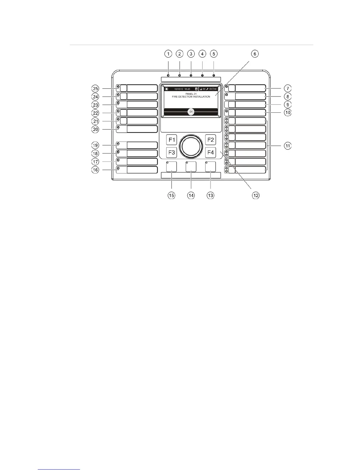
14. Panel Silence button and LED
15. Sounder Start/Stop Button and LED
16. System Fault LED
17. Low Battery LED
18. Earth Fault LED
19. Supply Fault LED
20. Fire Protection Fault/Disabled/Test LED
21. Fire Protection Delay button and LED
22. Fire Protection On/Acknowledged button
and LED
23. Fire Routing Fault/Disabled/Test LED
24. Fire Routing Delay button and LED
25. Fire Routing On/Acknowledged button and
LED
See “Assigning an output group to a programmable buttonon page 90 for more
information on configuring programmable buttons.

Table of Contents

Other manuals for Aritech 2X Series

Questions and Answers:

Question and Answer IconNeed help?

Do you have a question about the Aritech 2X Series and is the answer not in the manual?

Aritech 2X Series Specifications

General IconGeneral
CertificationsEN54-2, EN54-4
Power Supply230V AC, 50Hz
Battery Capacity7Ah
Current ConsumptionStandby: 50mA
Humidity RangeUp to 95% RH, non-condensing

Related product manuals