Chapter 1: Introduction
4 2X Series Installation Manual
Product overview
This topic provides an introduction to the control panel user interface, LCD,
operator controls, and indicators.
For a detailed overview of front panel controls and indicators, see “Front panel
controls and indicators” on page 6.
The user interface
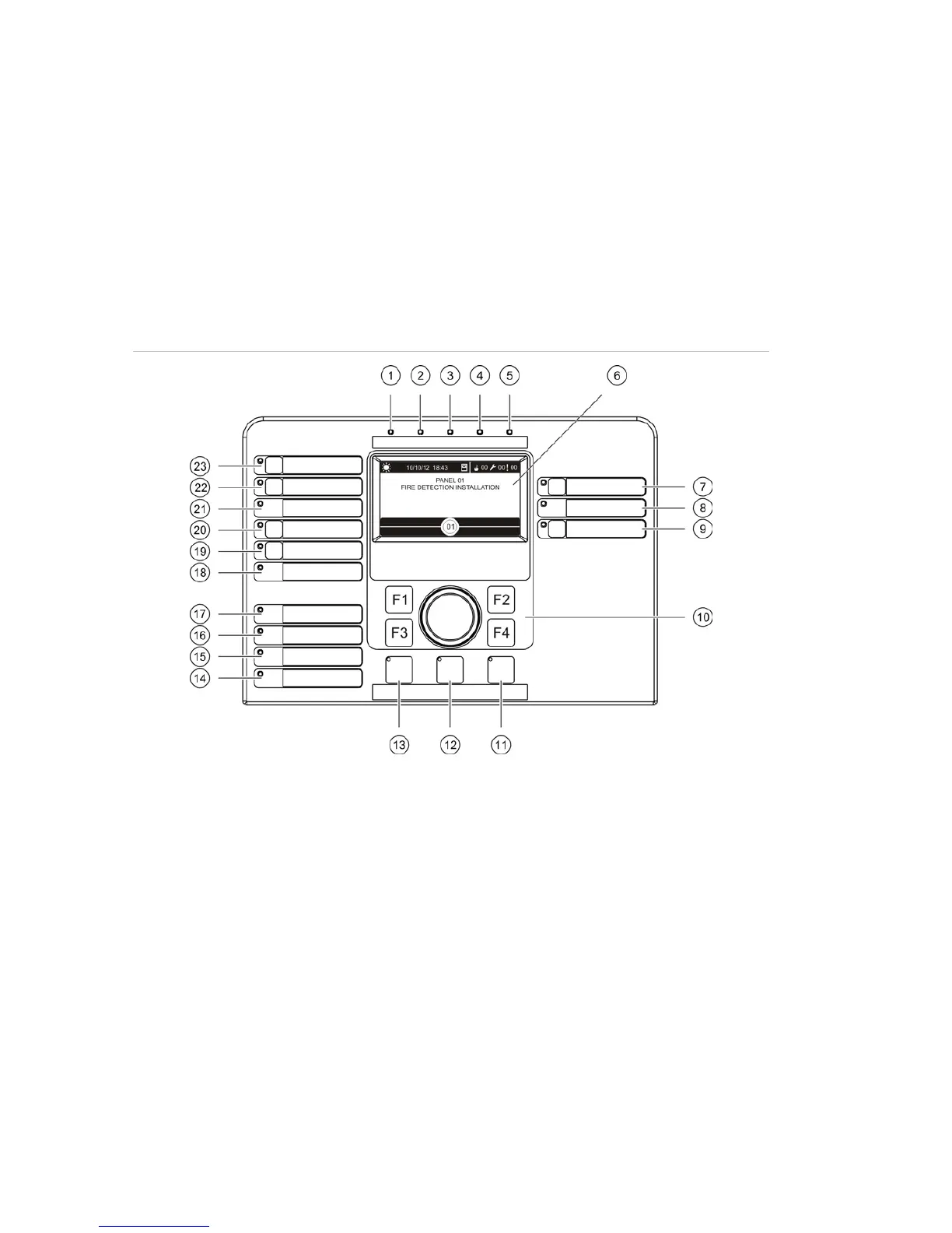
Figure 1: Fire panel user interface (with fire routing and fire protection controls)
. Sounder Delay button and LED
. Sounder Fault/Disabled/Test LED
. Reserved for future use
. Jog dial and function buttons
. Panel Silence button and LED
13. Sounder Start/Stop Button and LED
14. System Fault LED
15. Low Battery LED
16. Earth Fault LED
17. Supply Fault LED
18. Fire Protection Fault/Disabled/Test LED
19. Fire Protection Delay button and LED
20. Fire Protection On/Acknowledged button
and LED
21. Fire Routing Fault/Disabled/Test LED
22. Fire Routing Delay button and LED
23. Fire Routing On/Acknowledged button and