1508685 Rev D CHP Max Element Management Modules CHP-CMM, CMM-1, SMM, and SMM-1 6-15
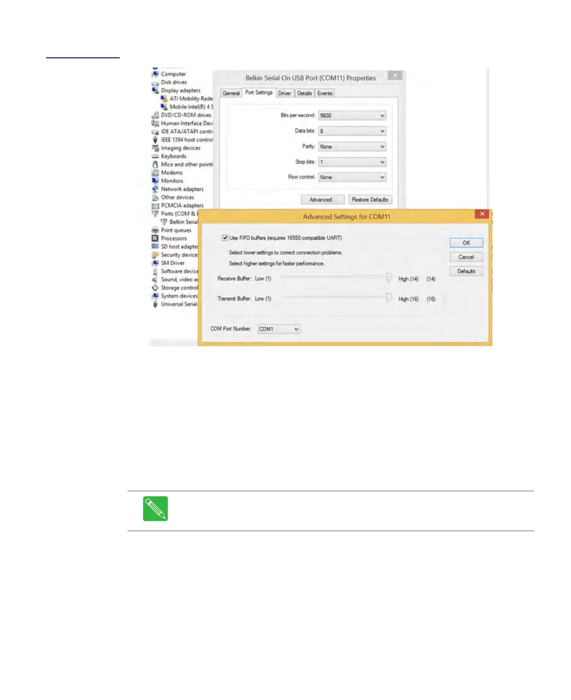
Figure 6.8
Advanced Settings
Window
13. Click on the OK button in the Advanced Settings window.
14. Click on the OK button in the USB-to-serial adapter cable Properties window.
15. Close the Device Manager window.
Connecting Chassis for Remote SNMP Monitoring
1. Connect an IP network cable from the RJ-45 Ethernet connector (standard CPE) on
the rear of each chassis containing the SMM to a remote management system. Refer
to your system design plans to connect the CHP network cabling. Figure 6.9 on page
6-16 represents a typical connection diagram with multiple SMM and CMM modules.
2. Connect cable (P/N CHP-XCT-CABLE) from one of the Shelf Interconnect connectors
on the rear of the chassis containing the SMM to one of the Shelf Interconnect
connectors of the closest chassis containing a CMM. The CHP-XCT-CABLE is not
provided and must be purchased separately.
Note When configuring the CHP network, only add one chassis to the daisy-chain
at a time and then use the shelfadd command to add the CMM shelf to the CHP
network.