3-8 CHP Max™ Headend Optics Platform Chassis, Controllers and Power Supplies Rev D
Functional Description
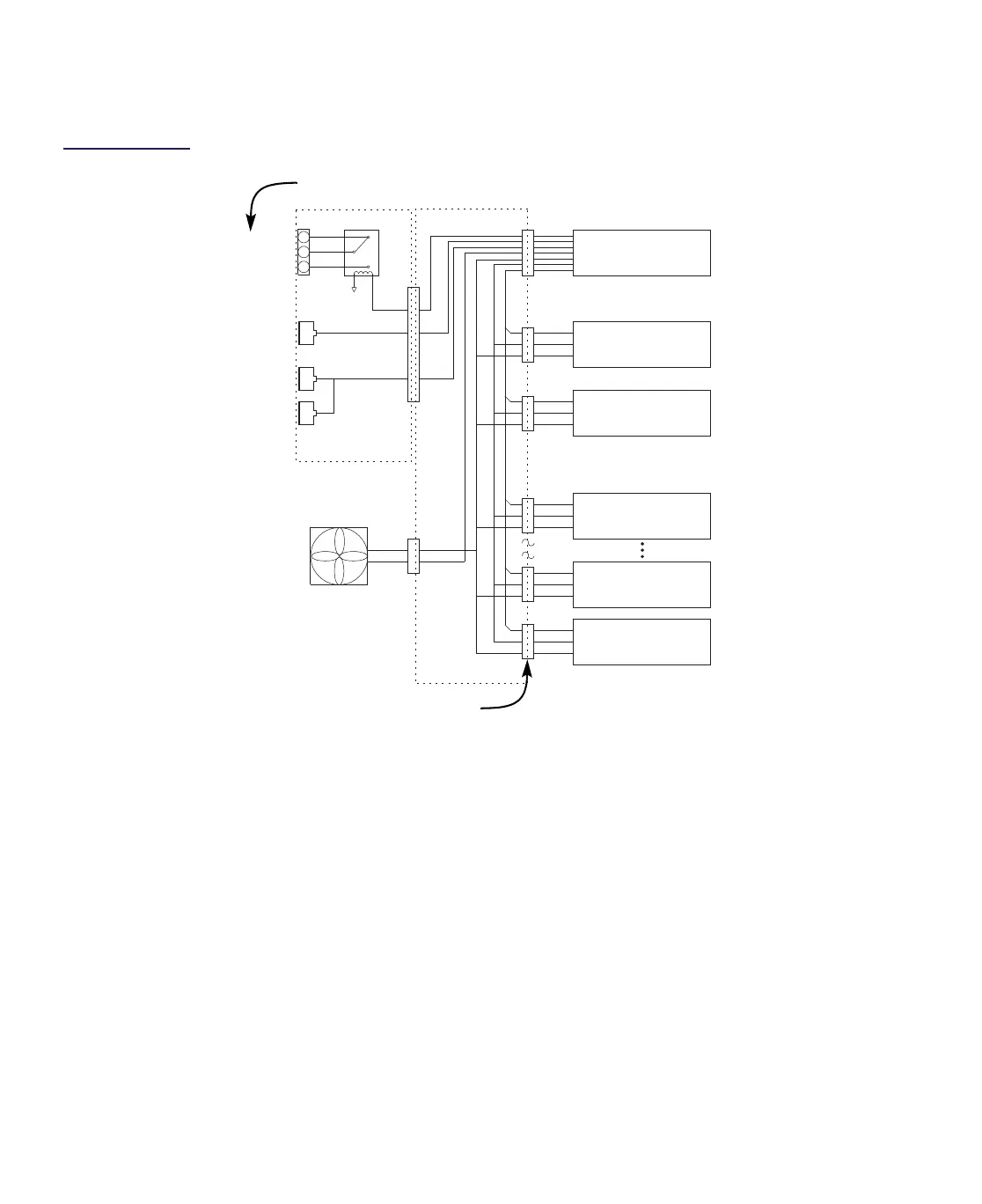
Figure 3.4
CHP Max5000
System Block
Diagram
DC Voltages
The CHP Max power supply feeds DC voltages into the backplane through a multi-pin
DC/Communications connector. These voltages travel along the DC power bus, entering each
application module through multi-pin DC/Communications Interfaces.
Management Signals
Local Monitoring
Craft Management Software is used to monitor a single CHP Max5000 chassis through a direct
RS-232 connection to the CMM or SMM. The CMM or SMM sends management signals
through the SPI bus on the chassis backplane to the other modules installed in the chassis,
and status information from the modules travels back through the same route; the CMM or
SMM then communicates with the computer running the Craft Management Software.
Shelf
Interconnect
SNMP
Ethernet
Local
Alarm
Com
N. O.
N. C.
Chassis Fan
(1 of 8
shown)
Aux Backplane
Main Backplane
Application Module 1
Application Module 2
Application Module
10
Power Supply 1
Power Supply 2
Management Module
(CMM or SMM)
Power Bus
Fan Current sense
SPI Bus
RS-485
Module Select Lines (12)
DC/Communications Interfaces
Please note that the contacts on the Local Alarm terminal block are reversed.