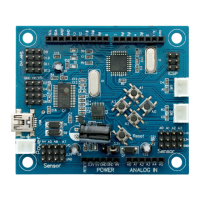
2
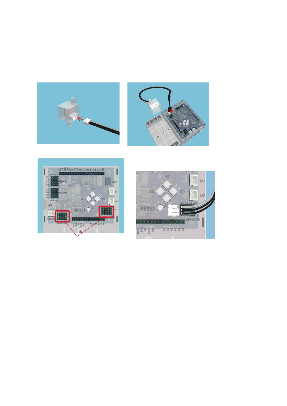
Sensor/LED/Buzzer Connectors
★
Sound Sensors, Light Sensors, and IR Photoreectors connect to A0 through A7.
★
Touch Sensors, LEDs, and Buzzers connect to A0 through A5.
★
Accelerometers use both A4 and A5 at the same time.
★
Push-buttons A0-A3 can’t be used when a sensor is connected to A0-A3.
The gray wires of your sensor connecting
cables should face towards the center of
the board.
Gray
Black
Black
A4 A5 A6 A7
A0 A1 A2 A3
2.2. Connecting Parts
①
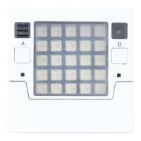
Connecting Sensors, LEDs, and Buzzers
The pictures below show how to plug sensor connecting cables into your Sensors, Buzzers, and
LEDs in order to connect them to your Studuino.
★
Every sensor uses a three-wire cable except for the Accelerometer, which uses a four-wire cable.