INSTALLATION GUIDE
Room Controller 4 (NIRC4-xMN) Optional Connections and Expansions
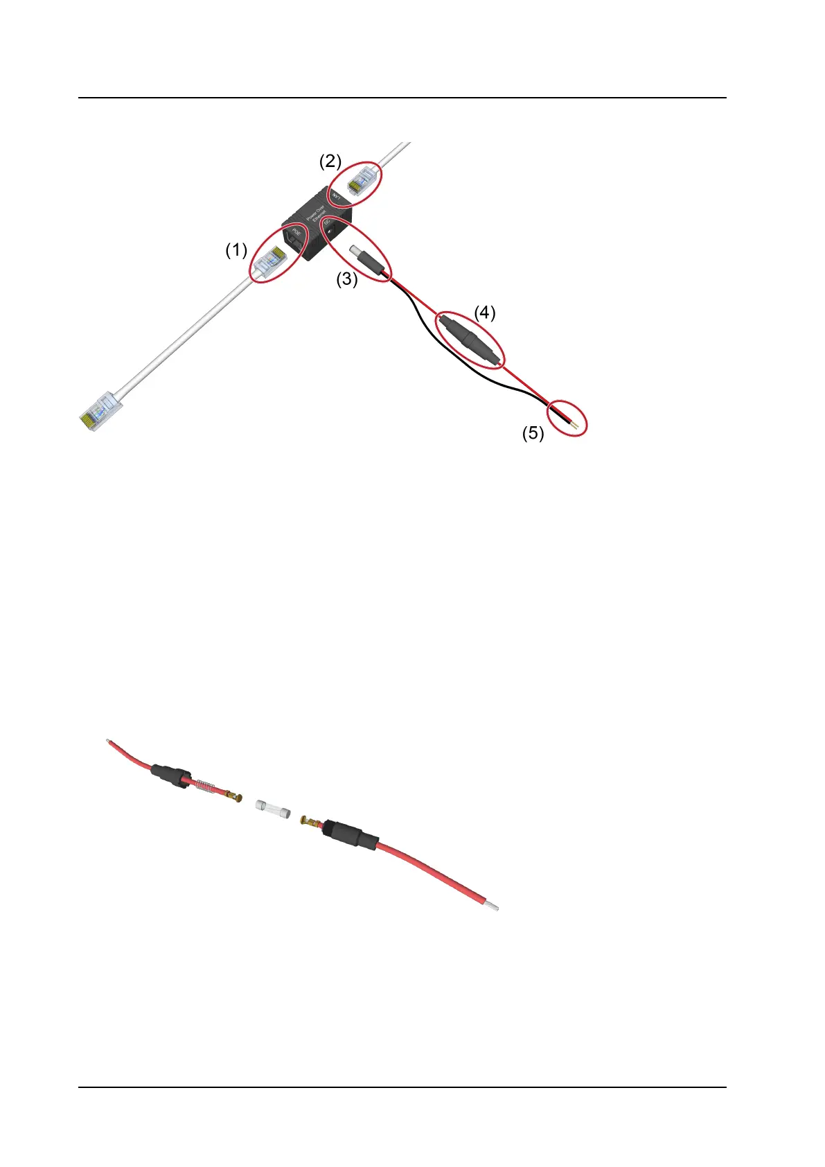
Figure 22. Passive PoE wall mount box
Legend
1. RJ-45 PoE socket to connect to NIRC4-xMN
2. RJ-45 LAN socket to connect to IP network
3. Power connector (Suitable for 5.5mm DC plugs)
4. Inline fuseholder with slow blow fuse 315mA
5. Wire leads to 24VDC power supply
To connect the power injector:
1. Use an inline fuseholder between the positive “+” terminal of the power supply and the power injector,
for example the Cooper Bussmann HHT inline fuseholder.
2. Unscrew the inline fuseholder and Insert a 5 x 15mm or 5 x 20mm - 315mA slow blow fuse into the fuse
holder.
3. Connect the wire leads (5) to the 24VDC power supply. The red wire connects to the positive “+”
terminal and the black wire to the GND “-” terminal.
4. Plug the RJ-45 LAN connector (2) into a LAN Socket that is connected to the IP network.
5. Connect the NIRC4-xMN to the RJ-45 socket (1) of the power injector using a short LAN patch cable.
TD 93351EN / 21 March 2022 / Ver. B
21