AC24/30/36 Operations Manual....
9
3 INTRODUCTION TO THE AC24, AC30, AC36, cont.
Being a unit designed from the ground up specifically for the yachting industry, all efforts have been
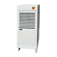
made to produce a system capable of sustaining the marine environment. All system components are
packaged in one stainless steel enclosure. Major components are internally modular, allowing a
simple exchange in the unlikely event of failure. Complete maintenance and service can be provided
with only top and front access to the converter. Two lightweight power modules can be removed
and replaced through the front panel for repair or power level upgrade.
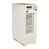
System operation is managed through two basic operators: a disconnect switch and membrane button
panel. A safety disconnect switch (red and yellow in color) near the top of the enclosure is used for
securing input service during maintenance and service. Three membrane button groups in the
control console, SHORE POWER, CONVERTER POWER, and SHIP’S POWER, provide normal
operation of the converter. The SHORE and CONVERTER switch groups contain ON and OFF
buttons with associated LED indicators; these buttons are used to turn ON and OFF the converter
input (SHORE POWER) and output (CONVERTER POWER). The SHIP’S group contains a
CONVERTER and GENERATOR button with associated LED indicators; these buttons are used to
manage Seamless Transfer when the option is included.
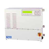
In addition to the basic function of power conversion, each converter provides the user with a
sophisticated power analysis and monitoring capacity. All parameters for input and output power,
along with operations and status information, are available on the front panel display console.
Various displays are selected through a long life, sealed membrane switch panel.
For additional information on controls and indicators, please refer to Section 6.