AC24/30/36 Operations Manual....
32
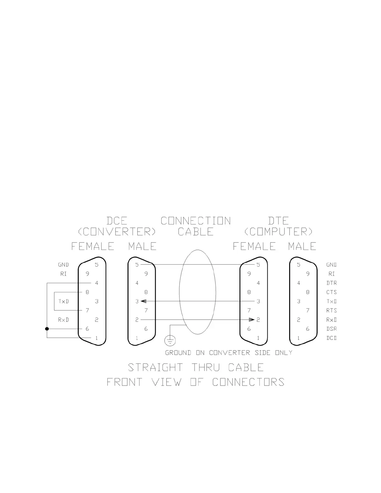
6.4 REMOTE COMMUNICATIONS
An ASEA converter can be controlled remotely through the use of its RS-232C serial interface. The
RS-232C serial port is made available at a DE9S connector (female, 9-pin D-subminiature) near the
base of the converter (see FIGURE 3 on page 19). The connector pinout used is industry-standard
for a 9-pin RS-232C DCE connection and given in FIGURE 6 below; note that hardware
handshaking in not supported. Also given in the figure below are the connections required from a
DCE to a DTE device (standard PC’s are configured as a DTE). Use of a shielded, jacketed, four-
wire (two twisted pairs), color-coded cable for each converter in the system is required.
The TxD signal originating in the converter is approximately +15V when “High” and -15V when
“Low.”
FIGURE 6 RS-232 PINOUT
The GND (ground) wire is connected to the chassis-ground of the converter.