step 17
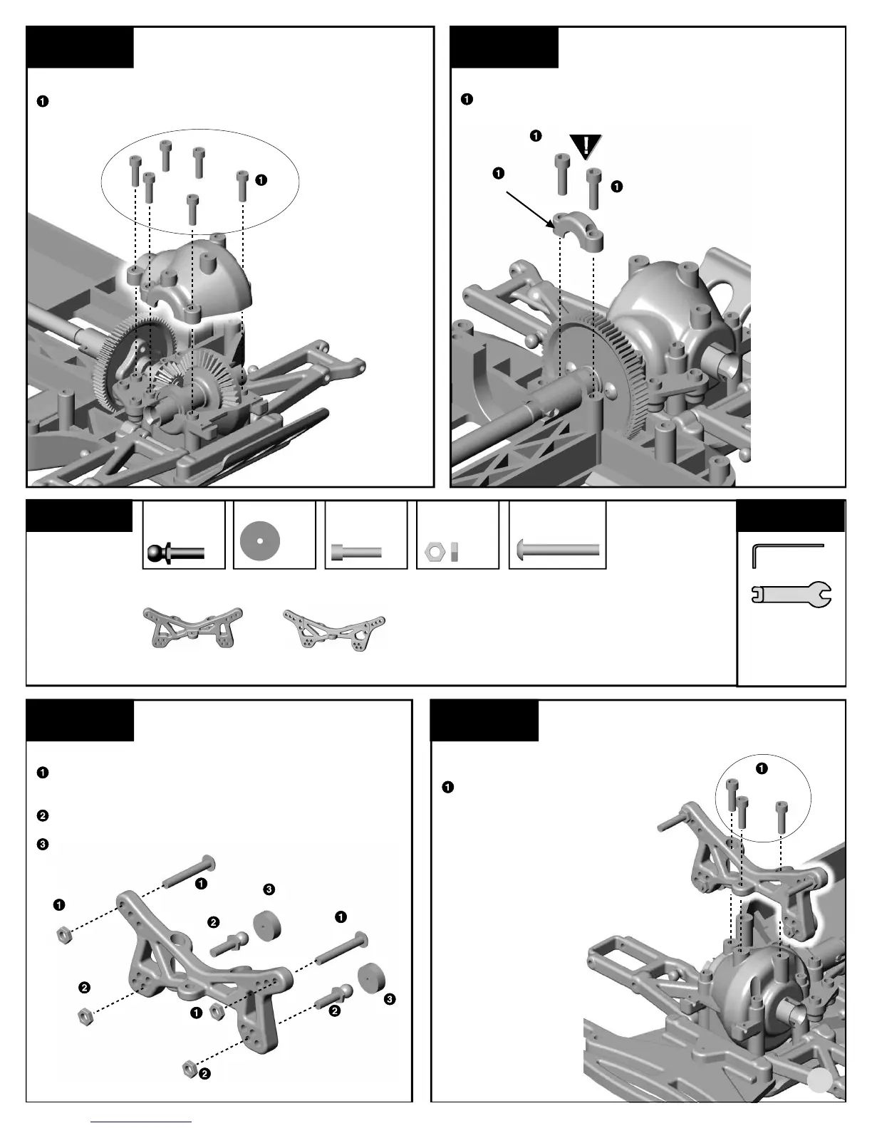
REAR TRANSMISSION CASE
Attach the #3910 upper transmission case to the lower
case with six #6924 (6860*) screws.
6924,
6860*
step 18
DRIVE BEARING CAP
Align the #3917 drive bearing cap over the bearing and
attach with two #6924 (6860*) screws where shown.
3917
Do not overtighten the #6924
(6860*) bearing cap screws.
6924,
6860*
6924,
6860*
BAG D
REMOVE THESE
PARTS FOR:
Steps 1-4
TOOLS USED
1:1
3858, qty 4
long special
ball end, black
step 1
FRONT SHOCK TOWER ASSEMBLY
Install the two #7413 screws through the outer holes on
the #3881 (3882*) front shock tower. Then thread on the
#7260 nuts.
Attach the #3858 ball ends and #7260 nuts through the
lower inner holes on the shock tower.
Add a #6272 dust cover to the ball ends.
6272, qty 4
ball end dust cover
6924, 6860*, qty 6
4-40 x 3/8 screw
7260, qty 8
4-40 plain nut
7413, qty 4
4-40 x 3/4 screw
3881, 3882*, qty 1
front shock tower
3895, 3896*, qty 1
rear shock tower
1:1 1:1 1:1
7413
7413
7260
7260
3858
3858
7260
7260
6272
6272
3881,
3882*
step 2
FRONT SHOCK TOWER
ASSEMBLY
Attach the #3881 (3882*)
front shock tower to the
upper transmission case with
three #6924 (6860*) screws.
6924,
6860*
1/16", 3/32"
1:1
3881,
3882*
11