3865, qty 4
set screw
3865
3865
6292,
6934*
6292,
6934*
FT KIT ONLY
3971*, qty 4
1/8 x 1/4 steering rack bearing
1:1
droop gauge
BAG A
TOOLS USED
4
3863
step 2
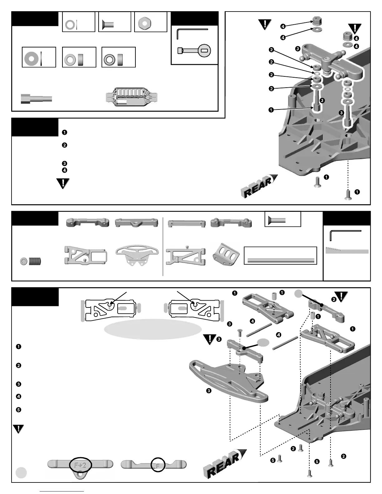
RACK TO CHASSIS ASSEMBLY
Install the two #3856 rack posts to the chassis with two #6291
screws.
Slide one #3856 washer, one #3856 steering rack bushing (3971*
bearing), one #3856 rack post shim and one #3856 bushing
(3971*
bearing)
onto the rack post. Repeat for the other post.
Place the rack assembly over the rack posts.
Add two #3856 washers, then the two #6222 nylon locknuts.
Tighten each nut down until the rack does not move
side-to-side freely. Then loosen the nuts 1/4 turn or until
the rack moves freely.
1:1
REMOVE THESE
PARTS FOR:
Step 2
3856, qty 2
rack post
6291, qty 2
4-40 X 1/4 screw
3856, qty 4
washer
3856, qty 4
1/8 x 1/4 steering
rack bushing
3856, qty 2
rack post shim
6222, qty 2
nylon locknut
3850, 3849*, qty 1
chassis
NOT IN BAG A
3856 rack post
3850,
3849*
6291
6291
3856 bushing
3971* bearing
3856 shim
3856 bushing
3971* bearing
6222
1:1
BAG B
REMOVE THESE
PARTS FOR:
Steps 1- 2
TOOLS USED
step 1
FRONT ARM ASSEMBLY
Install a #3865 set screw into the #3860 (3861*) front arms, right and
left sides. Thread the set screws into the arms until the set screws are
flush with the top of the arm. We will adjust them in step 3.
Attach the #3863 front arm rear mount (with the "F" molded into
mount--see below for location) to the chassis with two #6292
(6934*) screws.
Attach the #3863 front arm front mount (with the "F+2" molded
into the mount) to the #3851 bumper with one #6292 (6934*) screw.
Slide the #3866 inner hinge pins through the #3860 (3861*) front
arms. Slide the pins with the arms into the front arm rear mount.
Align the front arm front mount and bumper with the two hinge pins and slide
together. Tighten it down with two #6292 (6934*) screws.
By changing arm mounts you can adjust for kickup and anti-dive. For more
information about kickup and anti-dive settings, see the tuning section at the
rear of the manual.
3863, qty 1, code (F)
front arm rear mount
3863, qty 1, code (F+2)
front arm front mount
3863, qty 1
code R+3+2
rear arm rear mount
3863, qty 1, code (R)
rear arm front mount
1:1
6292, 6934*, qty 9
4-40 X 3/8 screw
3860, 3861*, qty 2
front arm
3851, qty 1
front bumper
3890, 3891*, qty 2
rear arm
3900, qty 1
rear bumper
3866, qty 4
inner hinge pin
3863
6292,
6934*
3851
6292, 6934*
6292,
6934*
3866
3866
3860,
3861*
3860, 3861*
1:1
3856 washer
3856 washer
1:1
1/16"
1/16", 3/32"
WHERE TO FIND THE ARM MOUNT CODE
(See page 20 for full explanation of arm mount codes)
F+2
F
REMOVE GRAY AREAS WHERE SHOWN
BE CAREFUL NOT TO REMOVE THE BALLS!!
Remove flashing so balls are perfectly smooth.
DO NOT REMOVE!!
1:11:1