24
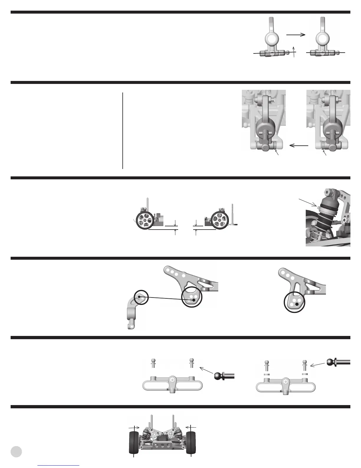
REAR ANTI-SQUAT describes the angle
at which the rear suspension is mounted in relation
to horizontal when looked at from the side of the car.
The TC3 comes standard with 2° of rear anti-squat.
This provides good rear traction. Installing the #3864
(R3+0) rear arm mount reduces anti-squat to 0° and
will reduce rear traction. However, it will improve ac-
celeration in bumpy conditions and increase steering
slightly.
REAR ARM MOUNT INFORMATION
code effect part #
R #3863 (std)
R+3+2 3° toe-in & 2° anti-squat #3863 (std)
R+3+0 3° toe-in & 0° anti-squat #3864 (optional)
R+2+0 2° toe-in & 0° anti-squat #3864 (optional)
R+2+2 2° toe-in & 2° anti-squat #3864 (optional)
0° anti-squat will reduce
rear traction, but im-
prove steering slightly.
2° of anti-squat
is kit standard.
FRONT
REAR TOE-IN is adjusted by changing the rear
arm mounts. The TC3 comes standard with 3° of toe-
in on each side. This setting should work best in any
condition. However, if less toe-in is desired, install
the #3864 (R+2+2) or #3864 (R+2+0) rear arm
mounts. These mounts have 2° of toe-in and will de-
crease rear traction and add steering. (See rear anti-
squat details above for more info on the mounts.)
CAMBER LINK LOCATIONS on the
TC3 have been thoroughly tested to find the best all
around positions. We suggest using the standard
setting for all conditions. However, if you must make
adjustments, the following guidelines should help you:
The longer or higher the link, the more traction and
less stability. The shorter or lower the link, the less
traction and greater stability.
Camber link possibilities for the rear tower and
hub carrier. Standard setup shown.
Camber link possibilities for the front tower. Standard
setup shown.
WHEELBASE ADJUSTMENT can be
made to the TC3 by moving the two #4187 1/32” plas-
tic spacers on the outer rear hinge pins (next to the
hub carrier).
Moving the spacers to the front of the hub car-
rier will lengthen the wheelbase and decrease rear
traction.
Moving the spacers to the rear of the hub car-
rier will shorten the wheelbase and increase rear trac-
tion.
ACKERMAN is a term describing the effect of
the inside front wheel turning tighter than the outside
front wheel. The standard setup works best in most
conditions and is preferred by most of our Team driv-
ers.
By adding two .100” (2.5mm) spacers and the
longer #3858 ball ends to the steering rack, a more
aggressive steering feeling can be achieved. This is
because there will be less ackerman.
Optional ackerman.
For a more aggressive steering feeling.
Standard ackerman.
For a neutral steering feeling.
#3858
black
#3855
Spacers to rear
shorten your
wheelbase.
Spacers to front
lengthen your
wheelbase.
FRONT
#3858
black
short ball
end used
long ball
end used
CAMBER describes the angle the wheels ride
relative to the ground when looked at from the front
or back. Negative camber means that the tire leans
inward at the top. Positive camber means just the
opposite, and should not be used.
Negative camber means
that the tire leans inward at
the top. Change camber by
turning the camber link.
RIDE HEIGHT describes the height of the
chassis in relation to the surface it is sitting on. This
adjustment must be made with the chassis ready-to-
run but with no body. The #8846 shock preload spac-
ers are used for raising and lowering the ride height.
We suggest starting with about 1/4” (6.0mm)
clearance between the chassis and ground. Try us-
ing a slightly lower right height for high traction con-
ditions such as carpet racing. Do not use a ride height
lower than 5/32” (4mm).
For more tips on setting ride height, see next page.
Ideal ride height is be-
tween 1/4” (6.3mm)
and 5/32” (4mm).
Adjust preload spacers to change
your ride height.
We suggest using 2° of negative camber to start with.
For tips on setting camber, see next page.