step 5
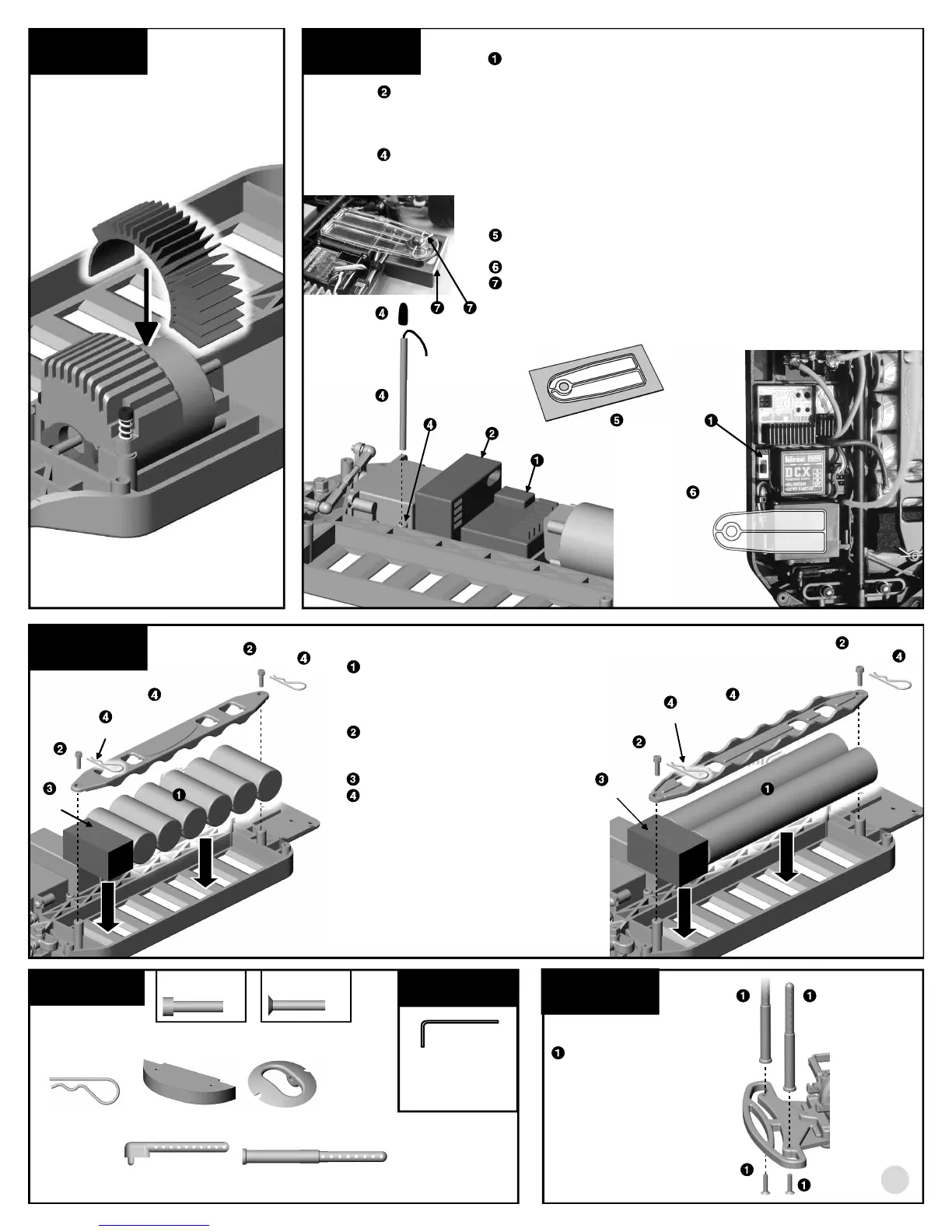
RADIO AND RECEIVER INSTALLATION
Cut a piece of #6727 servo tape and use it to attach your
optional ESC and switch where shown.
Cut a piece of #6727 servo tape and use it to attach your optional receiver where
shown.
Connect the ESC and steering servo to your receiver according to your radio or ESC
instructions. Then connect the motor to your ESC.
Push your receiver wire through the built-in antenna mount. Slide the wire through the
#6338 antenna and push the antenna firmly into the chassis antenna mount hole. Cap
the other end of the antenna tube and wire with the black rubber cap.
TRANSPONDER MOUNT
If needed, remove the transponder mount and cut away all the areas
shown in gray as shown in illustration.
Attach the mount to the servo where shown with servo tape.
FACTORY TEAM KIT ONLY: Push the #3968* counterfeit
transponder peg up through the hole in the mount and slide a #6332
body clip through the small hole on top of the mount.
ESC
receiver
6338
3
step 6
BATTERY INSTALLATION
Install your battery pack. See
which figure, at left or right, best
represents your battery
orientation.
Thread on the two #6916
screws. Aim the body clip hole
across the chassis.
Add the #3848 foam spacer.
Add the #3853 (3974*) battery
hold down strap, orienting it up
or down according to your
battery pack design. Adjust the
screws so the batteries are held
tight, but you are still able to
push the #6332 body clips
through the screws.
6916
6916
6916
6916
3853,
3974*
6332
6332
6332
6332
BAG I
REMOVE THESE
PARTS FOR:
Steps 1-2
7874, 7873*, qty 2
4-40 x 7/16 screw
1:1
6922, qty 2
4-40 x 1/2 screw
3897, qty 4
pivoting body mount
8874, qty 2
rear body post
6332, qty 8
body clip
6922
3848
3848
3852, qty 1
foam bumper
6338
8818
6922
1:1
switch
3902
cut out gray areas
attach
mount
here
19
8818, qty 2
front body post
TOOLS USED
1/16"
step 1
FRONT BODY
POSTS
Attach each
#8818 front body
post to the front
bumper with one
#6922 screw.
8818
step 4
FACTORY TEAM KITS ONLY:
Push the #3927* radial heatsink onto
the motor.
3853,
3974*
3968* 6332
3927*