2
TOOLS
KIT TOOLS SUPPLIED
EXTRA STUFF NEEDED
Phillips screwdriver #2
needlenose pliers
soldering iron (40-50 watts) and a
small amount of Rosin core solder.
Pencil-type soldering iron is better
than the gun type.
DANGER! Tip
is HOT!
Thread locking compound (#1596
Locking Adhesive or equivalent)
Super glue (cyanoacrylic glue,
#1597 Tire Adhesive).
hobby knife
WARNING!
This knife
cuts plastic and fingers with equal
ease, so be careful.
precision ruler
electrician's tape
strapping tape
Allen wrenches #6950 (.050",
1/16", 3/32", 5/64")
molded tools #6956
droop gauge #3987
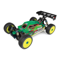
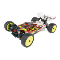
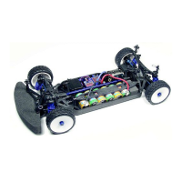
FACTORY TEAM KIT
Shocks: Blue anodized aluminum threaded shock
bodies, VCS Macro shocks.
Front & Rear Axles: Blue-anodized alloy MIP CVD's.
Turnbuckles: Factory Blue titanium turnbuckles.
Also includes: Precision PTFE-sealed ball
bearings. Droop gauge. Anti-roll bar. Factory Team
blue aluminum & graphite parts including:
Counterfeit transponder mount. Radial clip-on
heatsink. Graphite chassis. Unobtainium shock
shafts. Blue aluminum screws.
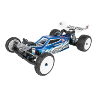
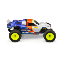
RACER KIT
Shocks: VCS Macro shock.
Tires and Wheels: Pro-Line V-Rage
tires and Axis wheels.
Front & Rear Axles: Composite MIP
CVD's.
Turnbuckles: Associated steel
turnbuckles
Choice of six Protoform bodies, with
Protoform decals.
Also includes: Precision stainless-
steel rubber-sealed ball bearings.
EACH KIT INCLUDES
Pro-Line standard 12m Hex wheels & tires (except Factory Team kits).
Aluminum motor mount with a built-in heatsink.
Carbide ball Stealth differentials.
Adjustable caster, camber, toe-in, anti-squat, kickup. Several tie-rod mounting
positions.
Foam bumper. TC3 decal sheet. Rear bumper.
HELPFUL TOOLS (NOT REQUIRED)
Allen drivers (straight Allen wrenches with hex shaped handles)
such as the following made by Associated:
#6957 .050" driver
#6958 1/16" driver
#6959 5/64" driver
#6960 3/32" driver
#6961 2.5mm driver
Vernier calipers
Hobby scissors
Nut drivers (screwdriver-
handled hex socket tools)
3/16" nut driver
1/4" nut driver
11/32" nut driver
WARNING!
Do not use a power screwdriver to install screws into nylon, plastic,
or composite materials. The fast rotation speed can heat up the
screws being installed. They can then break the molded parts or
strip the threads during installation.
ITEMS NEEDED TO COMPLETE YOUR CAR
1 R/C two channel surface frequency radio system.
2 *Battery pack (6 cell).
3 Battery charger (we recommend a peak detection charger).
4 *Electronic speed control.
5 *R/C electric motor.
6 *Pinion gear, size to be determined by type and wind of motor you
will be using.
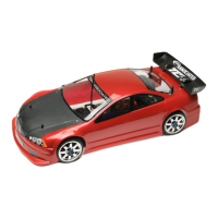
7 *1:10 scale Lexan body (Team & Factory Team Kits only).
8 *Touring car tires and wheels (Factory Team Kits only).
*Available from Team Associated. See your catalogs.
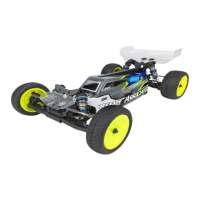
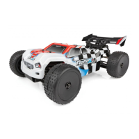
TEAM KIT
Shocks: Blue anodized aluminum-body
VCS Macro shocks.
Tires and Wheels: Pro-Line V-Rage
tires and Axis wheels.
Front & Rear Axles: Blue-anodized alloy
MIP CVD's.
Turnbuckles: Factory Blue titanium
turnbuckles.
Also includes: Precision stainless steel
[PTFE/rubber-sealed ball bearings.
LOCKING
ADHESIVE
0
1
2
3
4
5
6
7
8
WARNING! Always
use hand and eye
protection with cyano-
acrylic glue!