Mechanical Mounting Conditions LDM41A and LDM42A Manual
Page 14 ASTECH GmbH
4 Mechanical Mounting Conditions
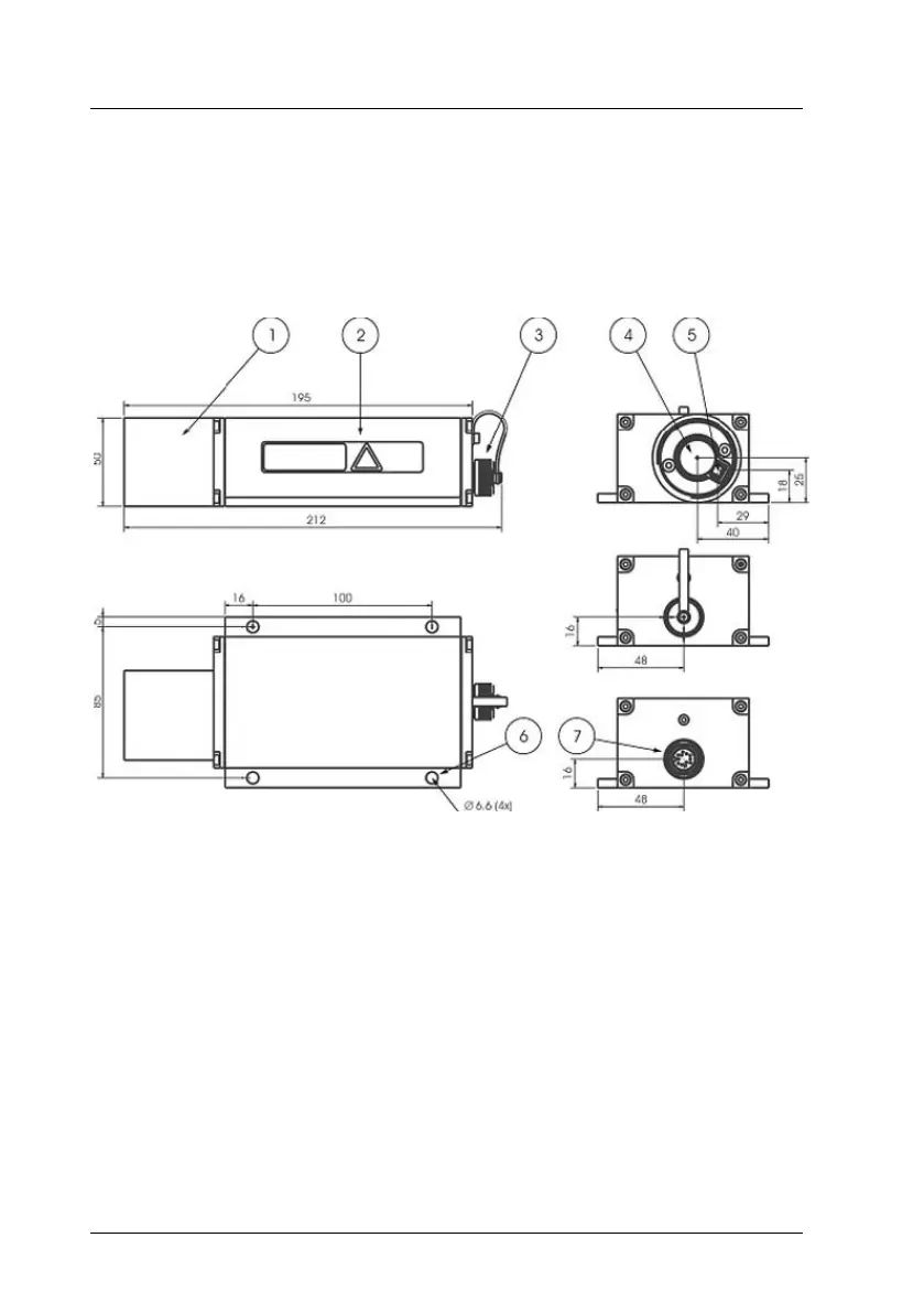
The casing consists of a rugged, corrosion-resistant extruded aluminum profile
with front-side and rear-side covers also in corrosion-resistant design. Four
mounting holes are provided in the base plate for mechanical attachment of
the LDM41A and LDM42A.
1 Equalizer tube at front cover
2 Casing
3 Protective cap for flange-mount connector
4 Receiver optics
5 Sender optics
6 Mechanical mounting holes (4x)
7 12-pole M18-flange-mount connector (Binder Serie 723)
Figure 3 : Dimensional drawing
To protect the sensor’s optical surfaces from dust, physical contact,
mechanical impacts, etc., the casing has a protection tube attached to it.
Optionally different protection windows and optical filters are available.