EasyManua.ls Logo

ASTECH LDM41A - 12 PC Interface Cable (Option)

ASTECH LDM41A
55 pages
Print Icon
To Next Page IconTo Next Page
To Previous Page IconTo Previous Page
Loading...
LDM41A and LDM42A Manual PC Interface Cable (Option)
ASTECH GmbH Page 51
12 PC Interface Cable (Option)
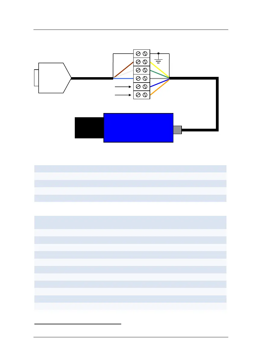
Figure 23 : RS232 cable with power supply for LDM41A and LDM42A
Table 11 : Pin assignment SUB-D 9 F
Nr. SUB-D 9 F
Color code
Designation SUB-D 9 F (PC COM)
Shield
-
Cable shield
3
brown
TxD
2
white
RxD
5
blue
GND
Table 12 : Pin assignment LDM41A and LDM42A
Pin LDM41A and
LDM-42A
Color code
Designation LDM41A and LDM42A /
RS232
Shield
-
Cable shield
A
green
TxD / RX+
B
yellow
RxD / RX-
C
27
brown
TRIG
D
red
IOUT
E
black
TX-
F
purple
TX+
G
orange
VCC
H
white
ALARM
J
grey
GND
L
blue
GND
RS232 Kabel: TXD and RXD are necessary to cross
27
Trigger function is not available for devices with internal heating (LDM41A-h and LDM42A-h)
GND
+24V
SUB-D 9 F

Table of Contents