Electrical Connection LDM41A and LDM42A Manual
Page 18 ASTECH GmbH
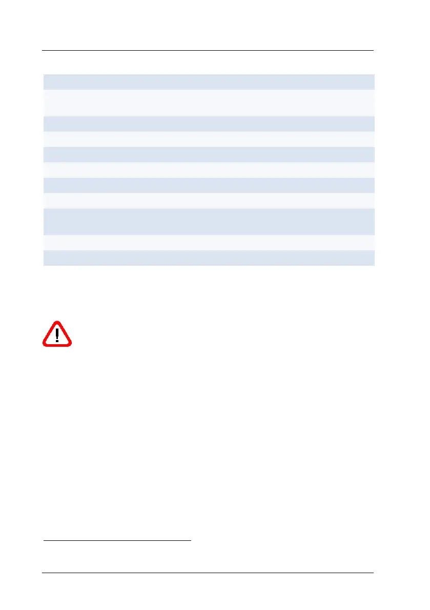
Table 2 : Pin assignment connector and interface cable
GND wires are connected to an internal collective ground point. They provide
the reference potential for all voltage values quoted below.
Caution: If input signals are applied to an output port, this may
damage the LDM41A and LDM42A!
Do not connect the current output IOUT (red) to the power supply
(10 ... 30 V). This will destroy the interface board!
For data communication via RS232, you are recommended to use cable 4
(grey, GND) for signal ground and cable 7 (blue, GND) for supply ground!
The limiting values of voltages, load rates and logic levels are in accordance
with RS232 and RS232 standard requirements.
All outputs are protected against steady short-circuit currents.
Trigger function is not available for devices with internal heating (LDM41A-h and LDM42A-h)
In case of interface cable with length of 10m the color of pin G, VCC can also be pink.