LDM41A and LDM42A Manual Interface Connection
ASTECH GmbH Page 43
Examples:
Distance = 4,996 m, SF1
dec: 004.996<CR><LF>
hex: <SPACE>001384<CR><LF>
(= 4996 mm × SF1)
dec+sig: 004.996_000005<CR><LF>
(bad signal quality)
dec+sig: 004.996_000985<CR><LF>
(good signal quality)
Distance = 4,996 m, SF10
dec: 049.960<CR><LF>
hex: _00C328<CR><LF>
(= 49960 = 4996 mm × SF10)
dec+sig: 049.960_000005<CR><LF>
Error case
dec/hex: E15<CR><LF>
(see page 50, chapoter 11, Error Codes)
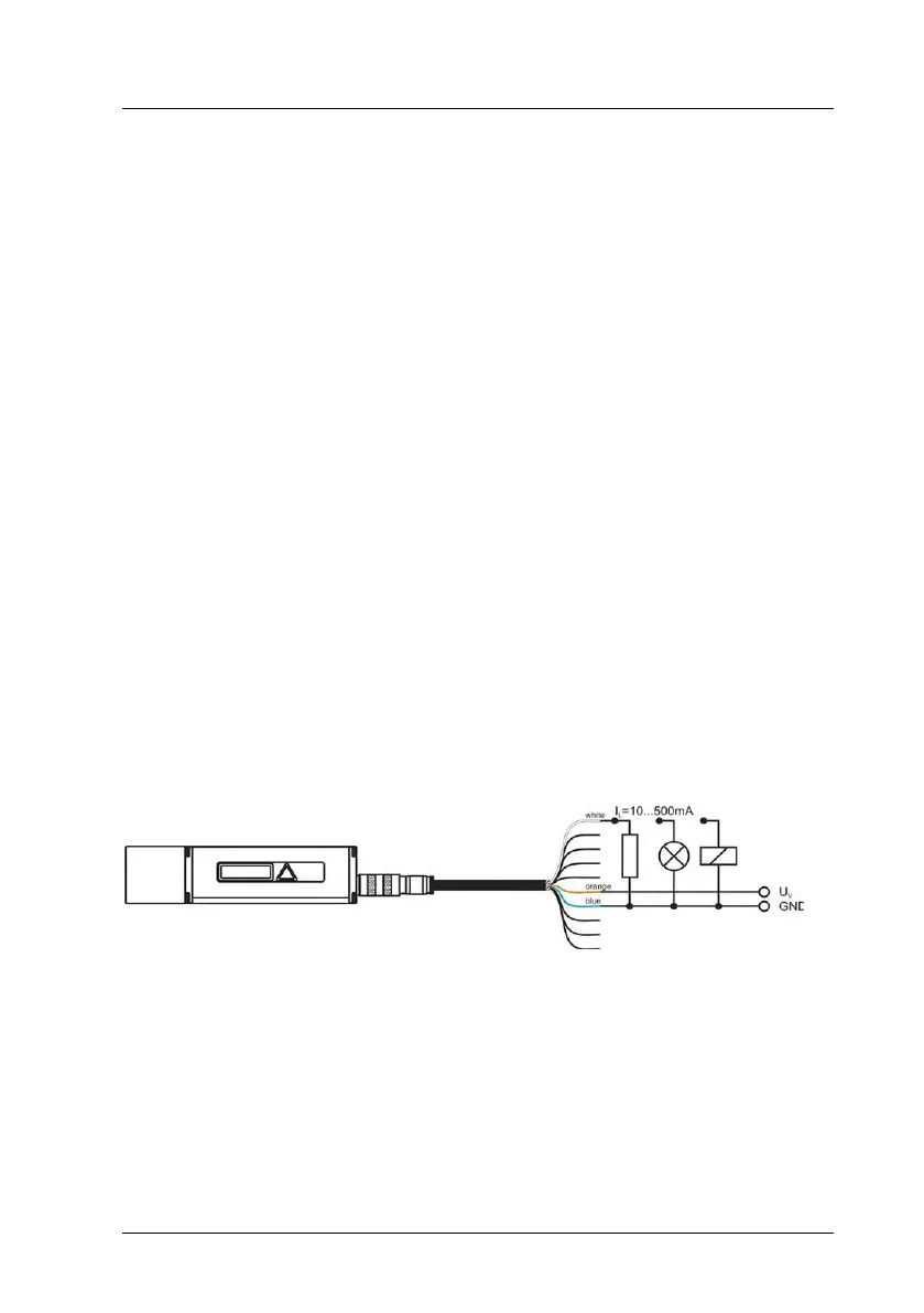
9.4 Digital Switching Output (Alarm)
With the help of a user-selectable distance threshold, the switching output
can be set to monitor objects or conditions for positive or negative overstep.
Figure 18 : Wiring diagram of digital switching output
For example, using the digital switching output, an object which was selected
for measurement can be monitored for excision of a threshold value. To do
this, parameter settings for a measurement window are required. Settings for
this window can be made via the three parameters: Alarm Center (AC), Alarm
Hysteresis (AH) and Alarm Width. The range which will be subject to
monitoring begins at AC and ends at AC+AW. Switching transitions can be set
via parameter AH.