LDM41A and LDM42A Manual Interface Connection
ASTECH GmbH Page 47
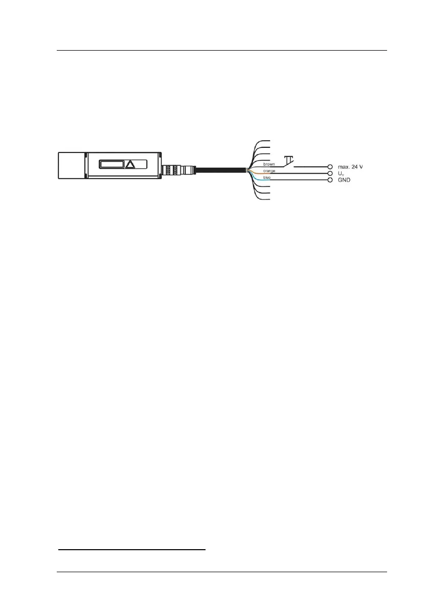
9.6 Trigger Input
The trigger input is intended for triggering a distance measurement with an
external signal that is applied as a voltage pulse between 3 V and 24 V. This
input is used only in trigger mode DF (DF – distance measurement with
external trigger)!
Figure 22 : Wiring diagram of trigger input
It is for the user to specify a desired delay time and a pulse slope to be
selected for synchronization (see 8.22, TDx y – display/set trigger delay trigger
level). The distance measurement will always be started with a delay of 5 ms
in addition with the programmed trigger delay time.
Having done this, the LDM41A and LDM42A has to be switched to trigger
mode (see 8.6, DF – distance measurement with external trigger).
Trigger function is not available for devices with internal heating (LDM41A-h and LDM42A-h)