LDM41A and LDM42A Manual Interface Connection
ASTECH GmbH Page 45
How the switching output is to behave on occurrence of an error message
(E15, E16, E17, E18) can be defined by making suitable settings under “SE“
(see 8.13, SE – display/set error mode [0/1/2])
9.5 Analog Output
The purpose of the analog output is to allow transmission of analog measured
values via a 4..20mA interface.
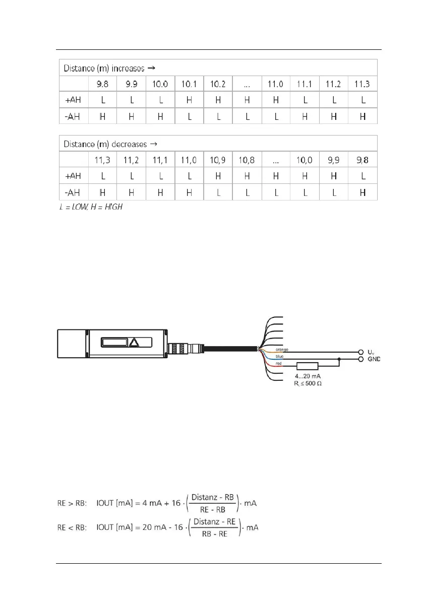
Figure 20 : Wiring diagram of analog output
The current is proportional to the measured target distance. This applies
within a distance interval that is marked by the two limiting parameters
“Range Begin“ (RB) and “Range End“ (RE), where RE may be greater or smaller
than RB (see 8.17 and 8.20)
The output current value is calculated according to this equation: