Chapter 4 Digital Output Settings (DIGITAL OUTPUT)
79
● DisplayPort Unit VM-1876A-M1
* The amount of data that can be transferred (pixel clock upper limit) differs depending on the combination of the link rate and
lane count. For details, refer to “4.2.2 DisplayPort Unit VM-1876A-M1”.
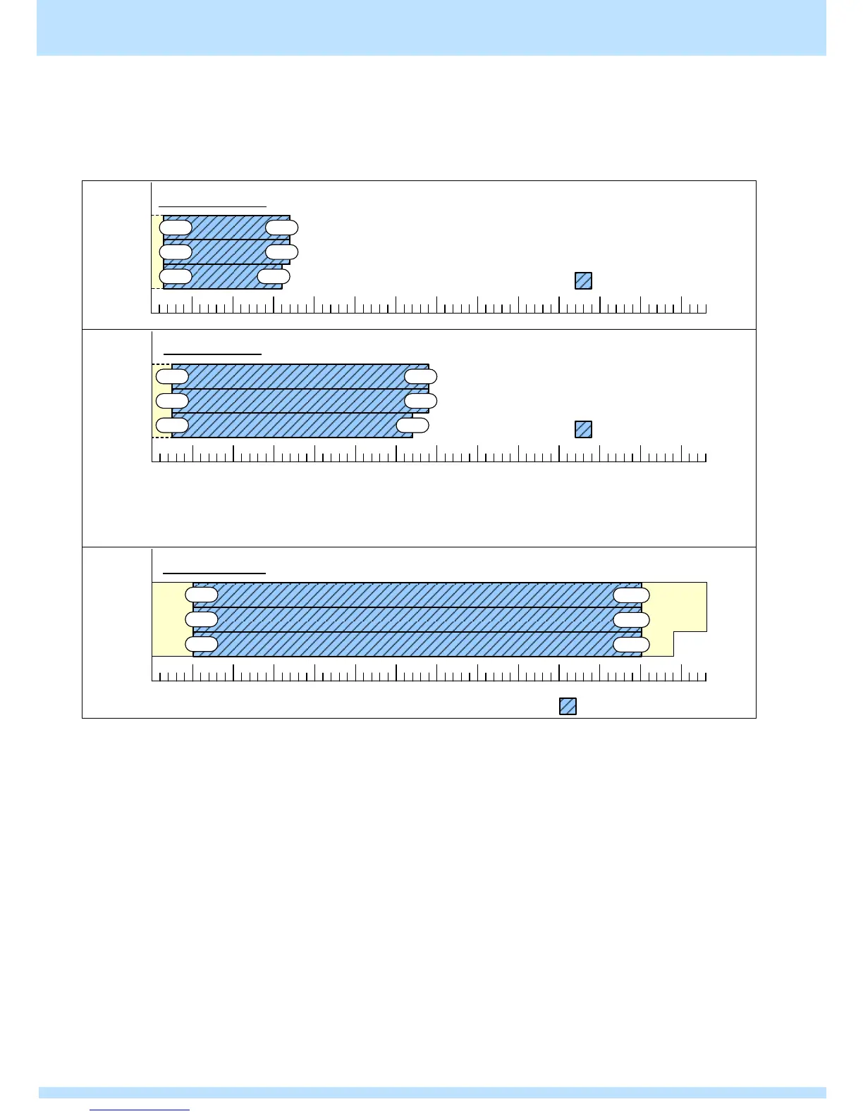
1) When the video width is 6 bits
11/12Bit
9/10Bit
8Bit
ColorDepth
1360MHz
シングルクロックモード
25M
25M
400MHz0.1MHz 800MHz 1200MHz1000MHz600MHz200MHz
25M
データが切り捨てられます
340M
320M
340M
50M
50M11/12Bit
9/10Bit
8Bit
ColorDepth
400MHz0.1MHz 800MHz 1200MHz 1360MHz1000MHz600MHz200MHz
50M
データが切り捨てられます
デュアルクロックモード
640M
680M
680M
The above displays the dot clock upper limit values when one image is output with two connectors (split rendering).
The dot clock upper limit values when one image is output with one connector are 8 bit: 600 MHz, 9/10 bit: 576 MHz, and
11/12 bit: 480 MHz.
100M
100M11/12Bit
9/10Bit
8Bit
ColorDepth
400MHz0.1MHz 800MHz 1200MHz 1360MHz1000MHz600MHz200MHz
100M
クアッドクロックモード
1200M
1200M
1200M
データが切り捨てられます