Chapter 4 Digital Output Settings (DIGITAL OUTPUT)
96
4.4 V-by-One HS unit functions and settings
The applicable unit is as follows.
4.4.1 V-by-One HS Unit VM-1876-M2
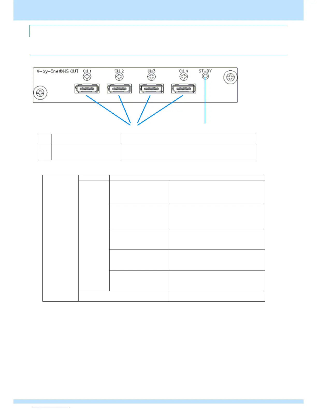
● Unit exterior diagram
The output of four lanes per connector can be performed.
Lights when output preparation is complete.
On: Normal
Off: Error (module damaged, wrong slot, etc.)
V-by-One HS
CH1
CH2
CH3
CH4
Number of data lanes: 1
lane
Single clock mode
8 bit: 20 to 85 MHz
10 bit: 20 to 85 MHz
12 bit: 20 to 75 MHz
Number of data lanes: 2
lanes
Single clock mode
8 bit: 40 to 170 MHz
10 bit: 40 to 170 MHz
12 bit: 40 to 150 MHz
Number of data lanes: 4
lanes
Single clock mode
8 bit: 80 to 340 MHz
10 bit: 80 to 340 MHz
12 bit: 80 to 300 MHz
Number of data lanes: 8
lanes
Dual clock mode
*1
8 bit: 160 to 680 MHz
10 bit: 160 to 680 MHz
12 bit: 160 to 600 MHz
Number of data lanes: 16
lanes
Quad clock mode
*2
8 bit: 320 to 1360 MHz
10 bit: 320 to 1360 MHz
12 bit: 320 to 1200 MHz
8/10/12 bit for each R, G, and B (RGB/YCbCr
supported)
*1 Uses CH1-CH2 (CH3-CH4) for 8-lane output.
*2 Uses CH1-CH2-CH3-CH4 for 16-lane output.