ASUS RS100-E9-PI2
4-25
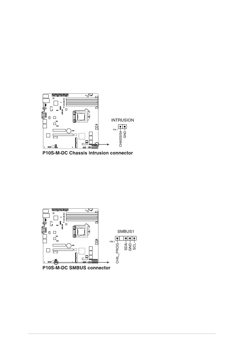
14. Chassis intrusion connector (2-pin INTRUSION)
Thisconnectorisforachassis-mountedintrusiondetectionsensororswitch.Connect
one end of the chassis intrusion sensor or switch cable to this connector. The chassis
intrusionsensororswitchsendsahigh-levelsignaltothisconnectorwhenachassis
componentisremovedorreplaced.Thesignalisthengeneratedasachassisintrusion
event.
Bydefault,thepinlabeled“ChassisSignal”and“Ground”areshortedwithajumper
cap.Removethejumpercapsonlywhenyouintendtousethechassisintrusion
detection feature.
15. System Management Bus (SMBUS) connector (5-1 pin SMBUS1)
This connector controls the system and power management-related tasks. This
connectorprocessesthemessagestoandfromdevicesratherthantrippingthe
individualcontrollines.