20
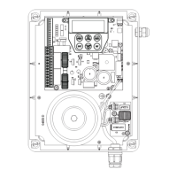
DCB-05V2 Gate Controller Owner Installation Instructions
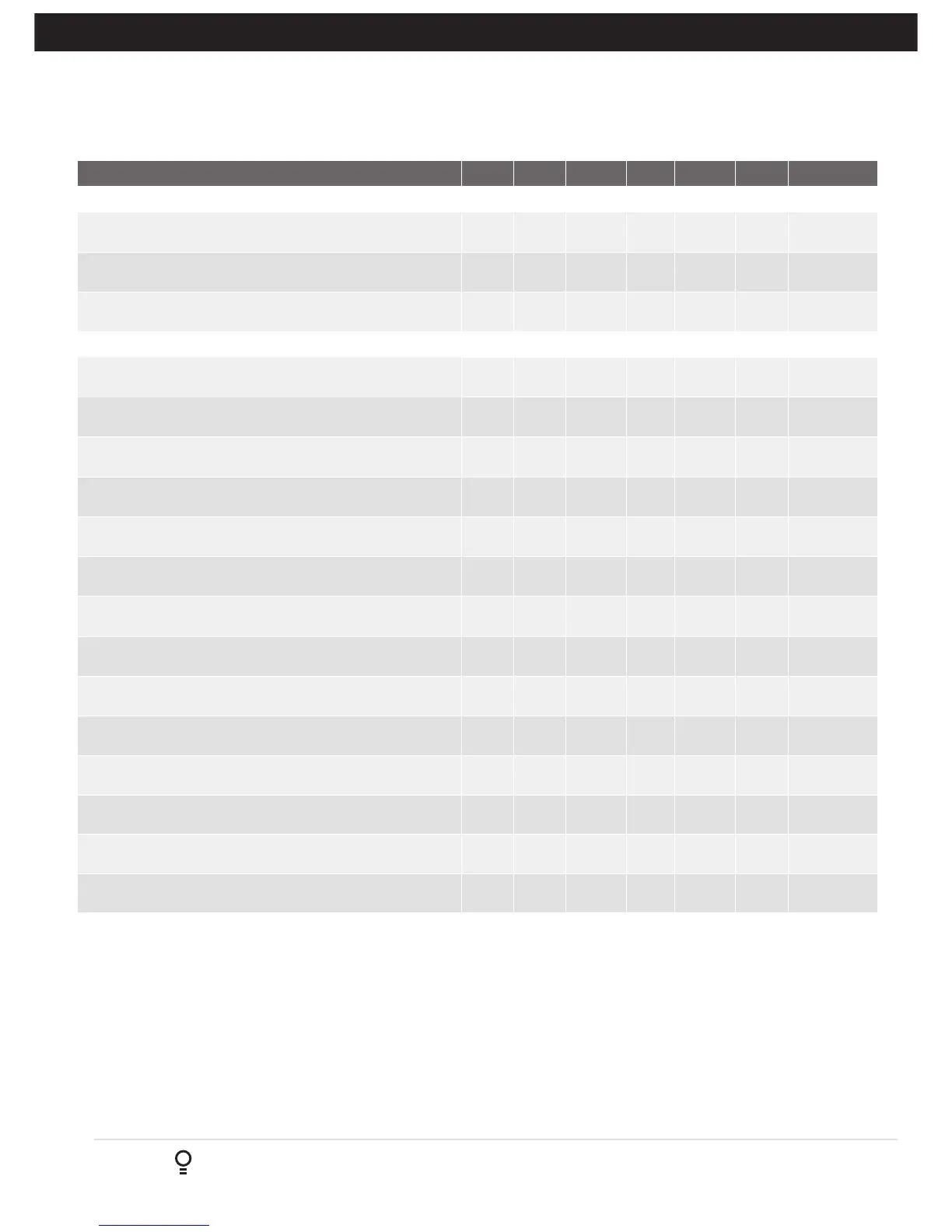
Parameter Min Max Default Step Unit Menu Section
Menu 5 - Light Times
ON AFTER CYCLE LIGHT TIME - Time light remains on for after a
cycle
0 255 60 1 Sec 5.1 14.2
ON BEFORE OPEN CYCLE LIGHT TIME
Minimum time light is activated for prior to opening
0 255 0 1 Sec 5.2 14.2
ON BEFORE CLOSE CYCLE LIGHT TIME
Minimum time light is activated for prior to closing
0 255 0 1 Sec 5.3 14.2
Menu 6 - Motor Settings
CLOSE SYNC DELAY TIME
Time delay between M2 and M1 closing
0.0 25.5 2.0 0.1 SEC 6.1 Appendix C
OPEN SYNC DELAY TIME
Time delay between M1 and M2 opening
0.0 25.5 2.0 0.1 SEC 6.2
OPEN SPEED VOLTS
Voltage applied to motors when opening
12 24 22 1 VOLTS 6.3
CLOSE SPEED VOLTS
Voltage applied to motors when closing
12 24 20 1 VOLTS 6.4
SLOW SPEED VOLTS
Voltage applied to motors when slowing down
6 24 8 1 VOLTS 6.5
SLOW TIME
The time between slow down and end of cycle
0.1 10.0 3.0 0.1 SEC 6.6
HOMING / SETUP SPEED VOLTS
Voltage applied to motors when setting up the travel limits
12 24 Norm 1 Volts 6.7
STOP PAUSE TIME
Pause time used between motor direction changes
0.0 2.0 0.3 0.1 SEC 6.8
M1 NORMAL OPEN TIME
Normal open time for motor 1
0.0 60.0 0.0 0.1 SEC 6.9
M1 NORMAL CLOSE TIME
Normal close time for motor 1
0.0 60.0 0.0 0.1 SEC 6.10
M2 NORMAL OPEN TIME
Normal open time for motor 2
0.0 60.0 0.0 0.1 SEC 6.11
M2 NORMAL CLOSE TIME
Normal close time for motor 2
0.0 60.0 0.0 0.1 SEC 6.12
M1 CLOSE DELAY
Close Delay for Motor 1
0.0 25.5 0.0 0.1 SEC 6.13
MAX OVERRUN TIME
Extra time allowed for cycle to complete (beyond normal cycle time)
0 60 5 1 6.14
A - Console Menu Structure
Appendix