38
Installation
Connections
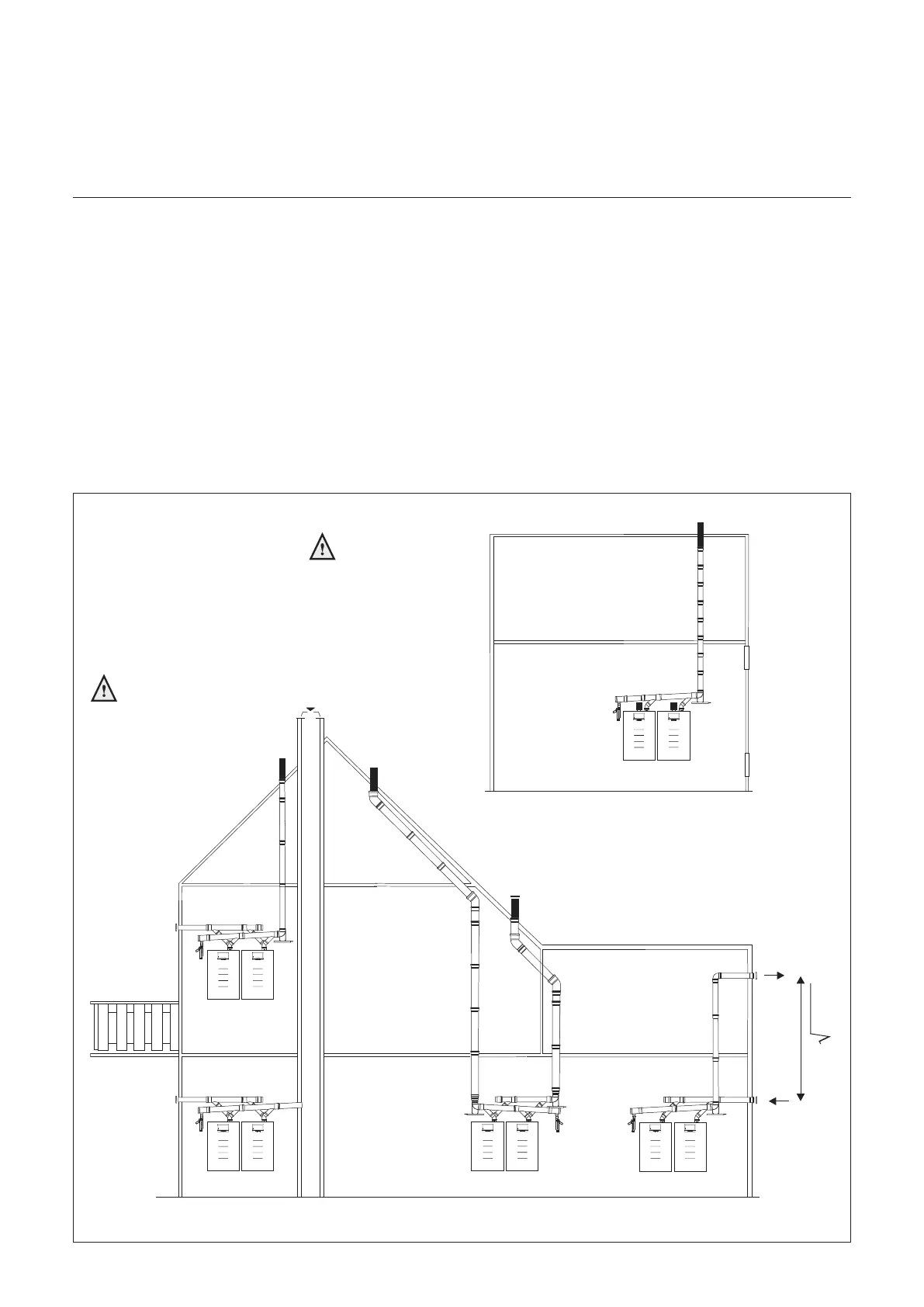
$LUÀXHJDVGXFWVLQVWDOODWLRQYDULDQWVIRUPXOWLSOHERLOHUV
2SWLQJIRUDFROOHFWLYHÀXHJDVRXWOHW
is determined by:
- The position of the boilers with
regard to their outlet area
6XႈFLHQWVSDFHDERYHWKHERLOHUV
- Number of boilers
You may opt for:
&ROOHFWLYHÀXHJDVRXWOHW
under-pressure
&ROOHFWLYHÀXHJDVRXWOHW
over-pressure
,QPDQ\VLWXDWLRQVÀXHJDVHVFDQQRW
be vented individually because the
installation is indoors. For such
situations, we recommend collective
venting by means of under-pressure or
RYHUSUHVVXUHXVLQJDÀXHJDVRXWOHW
system. The air supply may also be
supplied collectively, but if the boiler
room is suitable for that purpose it may
also be obtained from the boiler room
(`open device` Boiler category B).
If you install a common duct providing
combustion air to more than one
appliance, there is a risk that
combustion air would be drawn from an
other appliance.
This may then be subject to a
negative pressure.
In the case of collective venting
RIÀXHJDVHVWKHÀXHJDVYHQWLQJ
outlet always has to end up in the
open area (outlet area 1).
0,2 x 2 x B
Boiler category: B
Outlet area 1
(free outlet area)
Boiler category: C
Permitted only when the air
LQWDNHDQGWKHÀXHJDV
outlet are in the same
pressure area

 Loading...


