103
$SSHQGL[
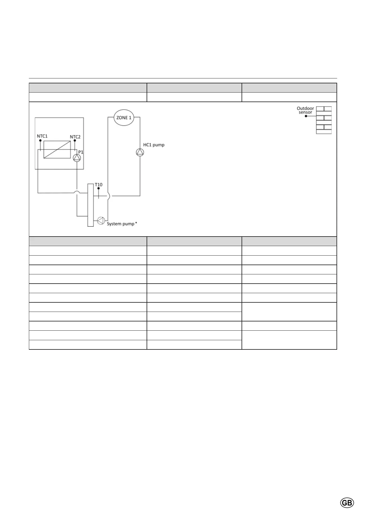
Standard schemes
Scheme Boiler group Distribution group
1 Single boiler or cascade One direct zone
Name and Description ECU I/O Note
%RLOHUÀRZVHQVRU NTC1
Boiler return sensor NTC2
Outdoor sensor NTC4
Boiler pump (230 V) P1
Boiler pump (PWM) PWM_P1
&RPPRQÀRZVHQVRU7 MTS1
HC1 pump MO1_HV
Pumps managed in parallel
System pump* MO1_HV
Heat request zone 1 PADIN1 or EBUS2
Alarm or sanitary pump VFR1
Optional
LPG/ Room supply Fan VFR3
*System pump: optional electrical connection. To use depending on application.

 Loading...


