44
Installation
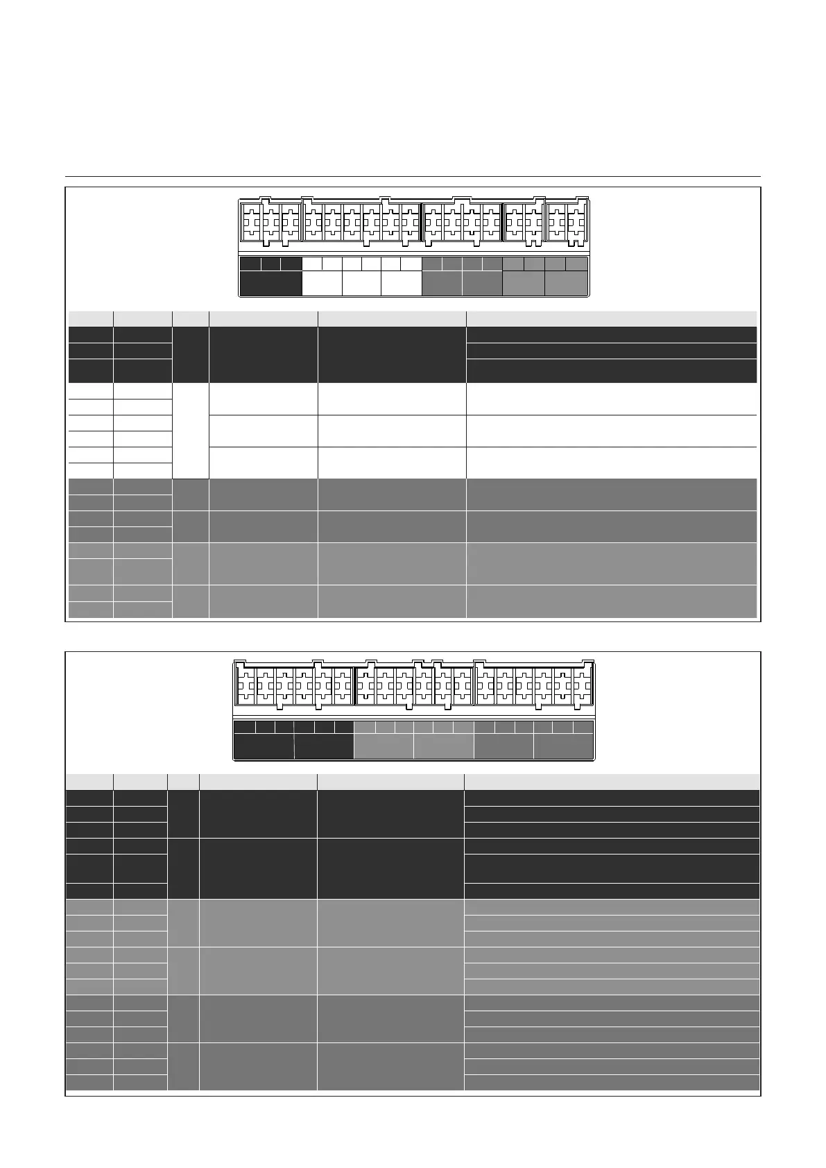
Electrical connection
Contact Line Type Name Function Description Electrical Description
1 PWM
MO1
Multifunctional
Output 1
DHW pump modulator
System Pump Modulator
Tank Filling pump Modulator
0..10 Volt feedback to BMS
3:0·N+]9KLJK 99ORZ9,KLJKP$
2 0-10 Volt 0..10 Volt
3 GND
4 NTC input
MTS1
Multifunctional
Temperature Input 1
T10 17&Nȕ
5 5 Volt
6 NTC input
MTS2
PMultifunctional
Temperature Input 2
LD%XႇHUWDQNWRSERWWRP
DHW circulation sensor*
17&Nȕ
7 5 Volt
8 NTC input
MTS3
Multifunctional
Temperature Input 3
LD%XႇHUWDQNWRSERWWRP
DHW charging sensor*
17&Nȕ
9 5 Volt
10 NTC input
NTC7
Outdoor sensor (T4)
Dedicated temperture
sensor for outdoor
17&Nȕ
11 5 Volt
12 NTC input
NTC3
Tank Sensor (T3)
Dedicated temperture for
DHW temperature
17&Nȕ
13 5 Volt
14 Signal
eBus
Input
eBus2
Communication bus for i.a.
cascade communication
/ thermostat / clib-in
15 GND
16 Signal
eBus
Output
eBus2
Communication bus for i.a.
thermostat / clib-in
17 GND
PWM 0-10V GND 5VNTC 5VNTC 5VNTC 5VNTC 5VNTC
Signal
GND
Signal
GND
MO1 (0-10V output) MTS1 (T10) MTS2 MTS3
NTC 7
(outd. sensor)
NTC 3 (DHW/
Tank sensor)
eBus eBus
Input OutputOutput Input Input Input Input Input
Contact Line Type Name Function Description Electrical Description
1 PWM
MO2
Multifunctional
Output 2
System Pump Modulator
Tank Filling pump Modulator
0..10 Volt feedback to BMS*
3:0·N+]9KLJK 99ORZ9,KLJKP$
2 0-10 Volt 0..10 Volt
3 GND
4 GND
PFDIN 1
Programmable
Frequency
Digital Input
DHW Flow meter or
RQRႇVLJQDO
GND
5 Signal
Digital: close with +24Vdc;
Frequency 0÷24V; max 400 Hz
6 24 Volt Power supply: +24Vdc, 10mA max
7 GND
PADIN 1
Programmable Analog
Digital Input 1
i.a. Heat generation lock
External consumer request
Room Thermostat 1*
GND
8 Signal Digital: close with +24Vdc; Analog: 0÷10V
9 24 Volt Power supply: +24Vdc, 10mA max
10 GND
PADIN 2
Programmable Analog
Digital Input 2
i.a. 0,,10 Volt temperture
request / power request
Room Thermostat 2*
GND
11 Signal Digital: close with +24Vdc; Analog: 0÷10V
12 24 Volt Power supply: +24Vdc, 10mA max
13 GND
PADIN 3
Programmable Analog
Digital Input 3
i.a. Heat generation lock
External consumer request
Room Thermostat 3*
GND
14 Signal Digital: close with +24Vdc; Analog: 0÷10V
15 24 Volt Power supply: +24Vdc, 10mA max
16 GND
PADIN 4
Programmable Analog
Digital Input 4
i.a. Heat generation lock
External consumer request
/RZZDWHUFXWRႇ
GND
17 Signal Digital: close with +5Vdc; Analog: 0÷5V
18 5 Volt Power supply: +5Vdc, 10mA max
GNDPWM 0-10V 24VSignalGND 24VSignalGND Signal 24VGND 24V 5VSignalGND GND Signal
PADIN 3 PADIN 4PFDIN 1 PADIN 1 PADIN 2MO2 (0-10V output)
InputInput Input InputOutput Input
4
3 & 5
See tables on pages 45-47.
See tables on pages 45-47.

 Loading...


