gure 33 - Connections to outdoor unit's terminal block
5.2 Electrical connections
on the outdoor unit side
Access to connection terminals:
• Alféa Extensa A.I. models 5, 6 and 8
- Remove the cowl.
• Alféa Extensa A.I. model 10
- Remove the front panel and cowl.
- Make the connections according to the diagram (gure
38, page 42).
- Use cable clamps to prevent any power cables from
being disconnected accidentally.
- Fill in the space where the cables enter the outdoor
unit with the insulating plate
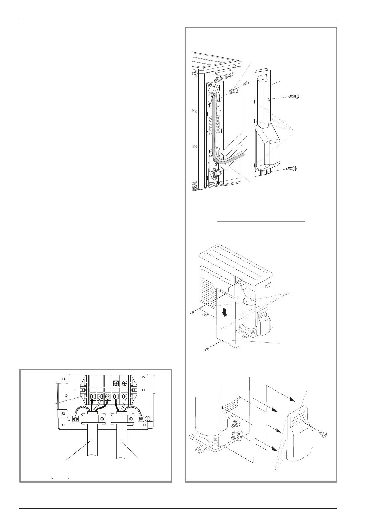
gure 34 - Access to outdoor unit's terminal block
Remove the cap
(1 screw)
Brackets (4 places)
Remove the
front panel
(2 screws)
Bracket
(3 places)
Déposer le capot
(2 vis)
Crochets
(4 endroits)
Câbles
Serre-Câble
Hooks (x4)
Hooks
(x3)
Remove the cowl
(1 screw)
Remove the front
panel
(2 screws)
Hooks
(4 places)
Cable clamp
Cable
Remove the cowl
(2 screws)
General power cable
Interconnection
between outdoor unit
and hydraulic unit
Terminal
Installation manual "1872 - EN"
Alféa Extensa A.I. Heat Pump
- 40 -
" Alféa Extensa A.I. 5, 6 and 8
" Alféa Extensa A.I. 10
 Loading...