" Before any maintenance operation, ensure that the general power supply is switched o.
" Electrical installation must be performed in accordance with current regulations.
5 Electrical connections
The electrical diagram for the hydraulic unit is shown on gure 51, page 78.
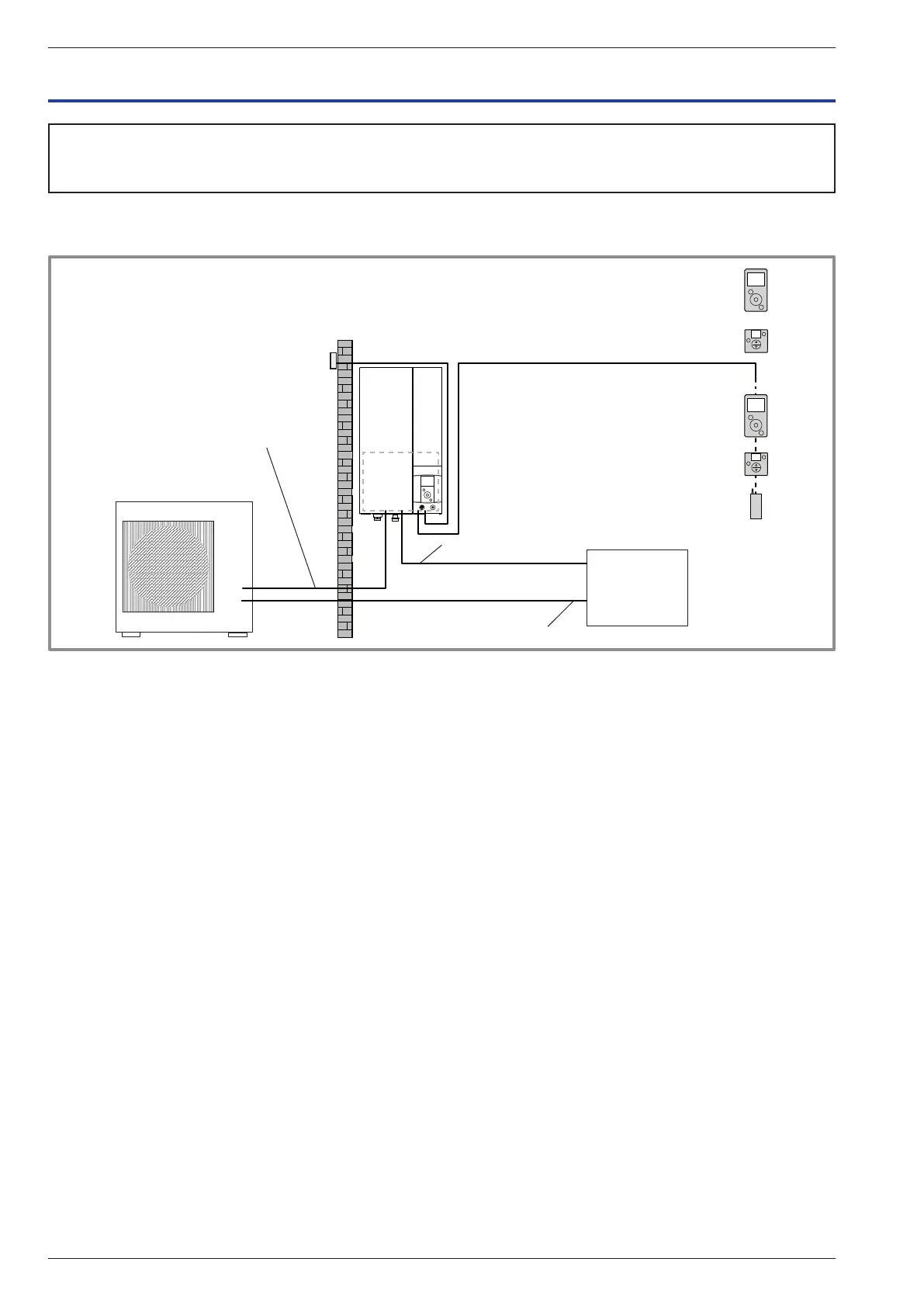
gure 32 - Overall layout of electrical connections for a simple installation (1 heating circuit)
Outside sensor
Cable 2 x 0.75 mm²
Electrical
Board
Electrical backup power supply (option)
(see table below)
General power supply
(see table below)
Interconnection between
outdoor unit and hydraulic unit
Phase, Neutral, Earth, Communication bus)
Cable 4 x 1.5 mm²
or
or
or
or
Room sensor A78 (battery/option)
Room sensor A59 (battery/option)
Room sensor A75 (option)
Cable 2 x 0.5 mm²
Room sensor A59 (option)
Cable 2 x 0.5 mm²
Typass ATL (option)
Cable 3 x 0.5 mm²
Installation manual "1872 - EN"
Alféa Extensa A.I. Heat Pump
- 38 -