57
7679H–CAN–08/08
AT90CAN32/64/128
ADC is used. To reduce power consumption in Power-down mode, the user can avoid the three
conditions above to ensure that the reference is turned off before entering Power-down mode.
7.2.2 Voltage Reference Characteristics
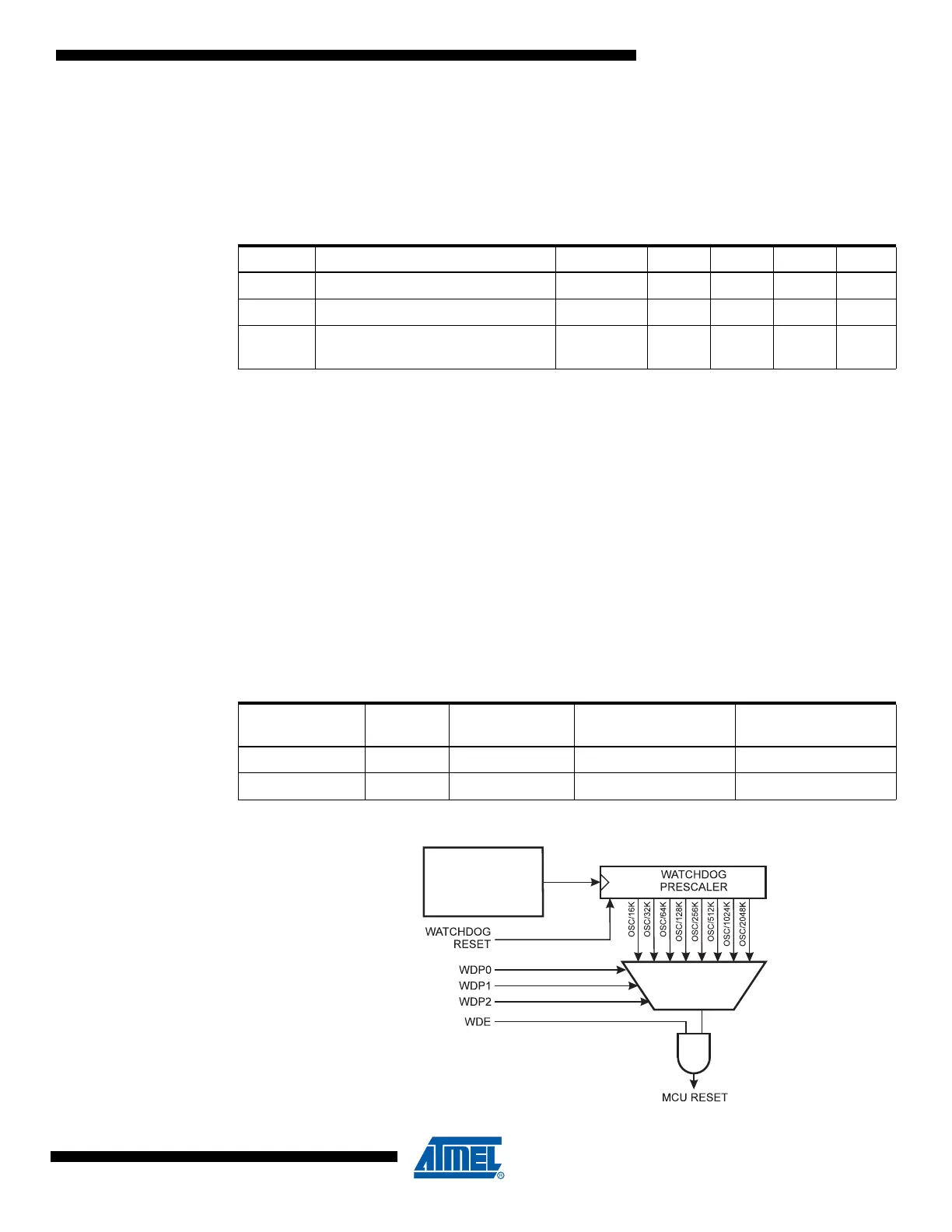
7.3 Watchdog Timer
The Watchdog Timer is clocked from a separate On-chip Oscillator which runs at 1 MHz. This is
the typical value at V
CC
= 5V. See characterization data for typical values at other V
CC
levels. By
controlling the Watchdog Timer prescaler, the Watchdog Reset interval can be adjusted as
shown in Table 7-6 on page 58. The WDR – Watchdog Reset – instruction resets the Watchdog
Timer. The Watchdog Timer is also reset when it is disabled and when a Chip Reset occurs.
Eight different clock cycle periods can be selected to determine the reset period. If the reset
period expires without another Watchdog Reset, the AT90CAN32/64/128 resets and executes
from the Reset Vector. For timing details on the Watchdog Reset, refer to Table 7-6 on page 58.
To prevent unintentional disabling of the Watchdog or unintentional change of time-out period,
two different safety levels are selected by the fuse WDTON as shown in Table 7-5. Refer to
“Timed Sequences for Changing the Configuration of the Watchdog Timer” on page 59 for
details.
Figure 7-7. Watchdog Timer
Table 7-4. Internal Voltage Reference Characteristics
Symbol Parameter Condition Min. Typ. Max. Units
V
BG
Bandgap reference voltage 1.0 1.1 1.2 V
t
BG
Bandgap reference start-up time 40 70 µs
I
BG
Bandgap reference current
consumption
15 µA
Table 7-5. WDT Configuration as a Function of the Fuse Settings of WDTON
WDTON
Safety
Level
WDT Initial
State
How to Disable
the WDT
How to Change
Time-out
Unprogrammed 1 Disabled Timed sequence Timed sequence
Programmed 2 Enabled Always enabled Timed sequence

 Loading...


