370
7679H–CAN–08/08
AT90CAN32/64/128
2. Required only for f
SCL
> 100 kHz.
3. C
b
= capacitance of one bus line in pF.
4. f
CK
= CPU clock frequency
5. This requirement applies to all AT90CAN32/64/128 Two-wire Serial Interface operation. Other devices connected to the
Two-wire Serial Bus need only obey the general f
SCL
requirement.
6. The actual low period generated by the AT90CAN32/64/128 Two-wire Serial Interface is (1/f
SCL
- 2/f
CK
), thus f
CK
must be
greater than 6 MHz for the low time requirement to be strictly met at f
SCL
= 100 kHz.
7. The actual low period generated by the AT90CAN32/64/128 Two-wire Serial Interface is (1/f
SCL
- 2/f
CK
), thus the low time
requirement will not be strictly met for f
SCL
> 308 kHz when f
CK
= 8 MHz. Still, AT90CAN32/64/128 devices connected to the
bus may communicate at full speed (400 kHz) with other AT90CAN32/64/128 devices, as well as any other device with a
proper t
LOW
acceptance margin.
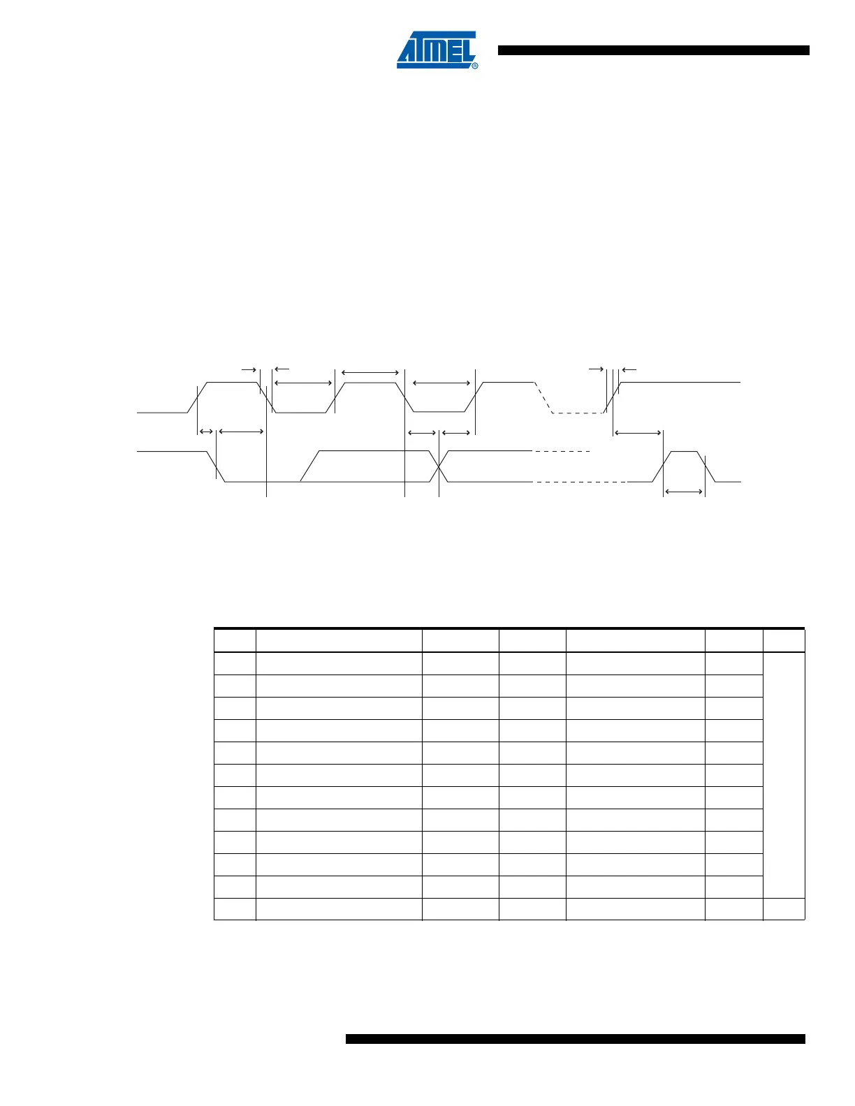
Figure 26-3. Two-wire Serial Bus Timing
26.6 SPI Timing Characteristics
See Figure 26-4 and Figure 26-5 for details.
t
SU;STA
t
LOW
t
HIGH
t
LOW
t
of
t
HD;STA
t
HD;DAT
t
SU;DAT
t
SU;STO
t
BUF
SCL
SDA
t
r
Table 26-4. SPI Timing Parameters
Description Mode Min. Typ. Max.
1 SCK period Master See Table 16-4
ns
2 SCK high/low Master 50% duty cycle
3 Rise/Fall time Master 3.6
4 Setup Master 10
5 Hold Master 10
6 Out to SCK Master 0.5 • t
sck
7 SCK to out Master 10
8 SCK to out high Master 10
9 SS low to out Slave 15
10 SCK period Slave 4 • t
ck
11 SCK high/low
(1)
Slave 2 • t
ck
12 Rise/Fall time Slave 1.6 µs

 Loading...


