174
7679H–CAN–08/08
AT90CAN32/64/128
and SPIF in SPSR will become set. The user will then have to set MSTR to re-enable SPI Mas-
ter mode.
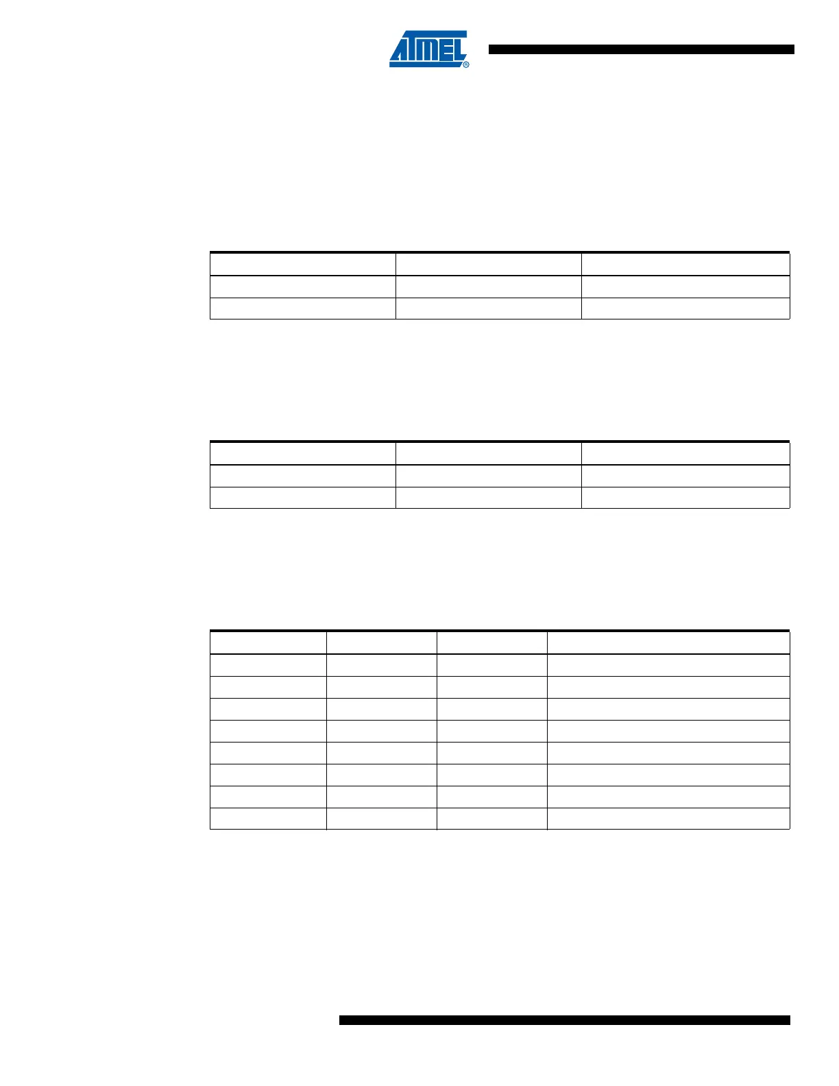
• Bit 3 – CPOL: Clock Polarity
When this bit is written to one, SCK is high when idle. When CPOL is written to zero, SCK is low
when idle. Refer to Figure 16-3 and Figure 16-4 for an example. The CPOL functionality is sum-
marized below:
• Bit 2 – CPHA: Clock Phase
The settings of the Clock Phase bit (CPHA) determine if data is sampled on the leading (first) or
trailing (last) edge of SCK. Refer to Figure 16-3 and Figure 16-4 for an example. The CPOL
functionality is summarized below:
• Bits 1, 0 – SPR1, SPR0: SPI Clock Rate Select 1 and 0
These two bits control the SCK rate of the device configured as a Master. SPR1 and SPR0 have
no effect on the Slave. The relationship between SCK and the clk
IO
frequency f
clkio
is shown in
the following table:
Table 16-2. CPOL Functionality
CPOL Leading Edge Trailing Edge
0 Rising Falling
1 Falling Rising
Table 16-3. CPHA Functionality
CPHA Leading Edge Trailing Edge
0 Sample Setup
1 Setup Sample
Table 16-4. Relationship Between SCK and the Oscillator Frequency
SPI2X SPR1 SPR0 SCK Frequency
000
f
clkio
/4
001f
clkio
/16
010
f
clkio
/64
011
f
clkio
/128
100
f
clkio
/2
101
f
clkio
/8
110
f
clkio
/32
111
f
clkio
/64

 Loading...


