325
7679H–CAN–08/08
AT90CAN32/64/128
• Allow software update in the entire Flash.
See Table 24-2 and Table 24-3 for further details. The Boot Lock bits can be set in software and
in Serial or Parallel Programming mode, but they can be cleared by a Chip Erase command
only. The general Write Lock (Lock Bit mode 2) does not control the programming of the Flash
memory by SPM instruction. Similarly, the general Read/Write Lock (Lock Bit mode 1) does not
control reading nor writing by LPM/SPM (Load Program Memory / Store Program Memory)
instructions, if it is attempted.
Note: 1. “1” means unprogrammed, “0” means programmed
Note: 1. “1” means unprogrammed, “0” means programmed
24.5 Entering the Boot Loader Program
Entering the Boot Loader takes place by a jump or call from the application program. This may
be initiated by a trigger such as a command received via USART, or SPI interface. Alternatively,
the Boot Reset Fuse can be programmed so that the Reset Vector is pointing to the Boot Flash
start address after a reset. In this case, the Boot Loader is started after a reset. After the applica-
tion code is loaded, the program can start executing the application code. Note that the fuses
cannot be changed by the MCU itself. This means that once the Boot Reset Fuse is pro-
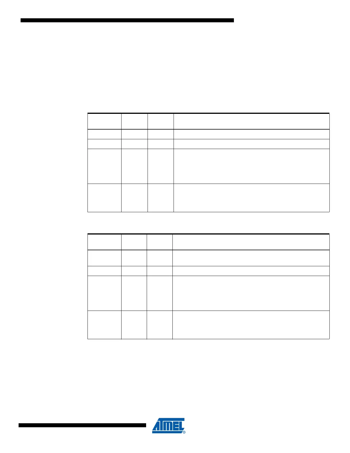
Table 24-2. Boot Lock Bit0 Protection Modes (Application Section)
(1)
Lock Bit
Mode
BLB02 BLB01 Protection
1 1 1 No restrictions for SPM or LPM accessing the Application section.
2 1 0 SPM is not allowed to write to the Application section.
300
SPM is not allowed to write to the Application section, and LPM
executing from the Boot Loader section is not allowed to read
from the Application section. If Interrupt Vectors are placed in the
Boot Loader section, interrupts are disabled while executing from
the Application section.
401
LPM executing from the Boot Loader section is not allowed to
read from the Application section. If Interrupt Vectors are placed
in the Boot Loader section, interrupts are disabled while executing
from the Application section.
Table 24-3. Boot Lock Bit1 Protection Modes (Boot Loader Section)
(1)
Lock Bit
Mode
BLB12 BLB11 Protection
111
No restrictions for SPM or LPM accessing the Boot Loader
section.
2 1 0 SPM is not allowed to write to the Boot Loader section.
300
SPM is not allowed to write to the Boot Loader section, and LPM
executing from the Application section is not allowed to read from
the Boot Loader section. If Interrupt Vectors are placed in the
Application section, interrupts are disabled while executing from
the Boot Loader section.
401
LPM executing from the Application section is not allowed to read
from the Boot Loader section. If Interrupt Vectors are placed in the
Application section, interrupts are disabled while executing from
the Boot Loader section.

 Loading...


