Installation Manual 58 Document #: LTRT-94704
Mediant 3000 & IPmedia 3000
3.3.3.2 Connecting Ethernet Interfaces to OAMP and Control IP Networks
Mediant 3000 housing 8410 blades supports Separate Physical Interfaces for Media,
Control, and OAMP (configured by the ini file parameter EnableNetworkPhysicalSeparation
- refer to the device's User's Manual).
Note:
The cabling of the PEM Ethernet ports for Control and Operations,
Administration, Maintenance, and Provisioning (OAMP) network interfaces
described in this section is applicable only to Mediant 3000 with 8410 blade.
The Media interface is provided by the Gigabit Ethernet port on RTM-8410 (refer to
''Connecting GbE Interfaces to IP Network'' on page 59). T
he Control and OAMP network
interfaces are provided by the 10/100BaseT Ethernet ports located on the two PEM
modules, as follows:
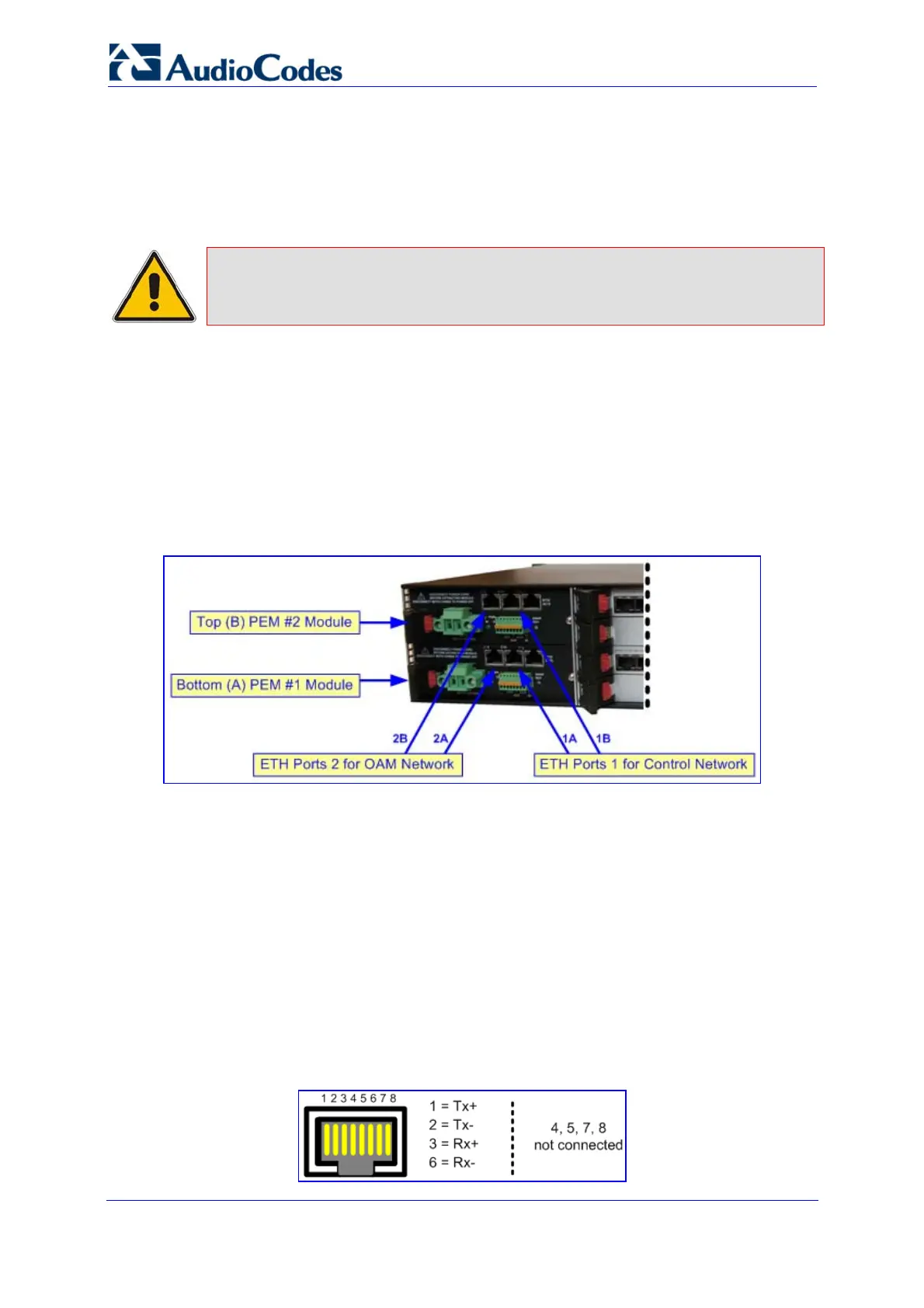
Control network traffic: Ethernet ports labeled 1A (bottom PEM module) and 1B (top
PEM module)
OAMP network traffic: Ethernet ports labeled 2A (bottom PEM module) and 2B (top
PEM module)
Figure 3-11: Cabling PEM Ethernet Ports to Control and OAM Networks
The dual ports per network interface type provide 1+1 redundancy. These ports connect
directly to the active 8410 blade in the chassis' front panel. The operating status of these
ports are provided by the ETH LEDs on the 8410 blade (refer to ''LEDs'' on page 28).
¾ To connect the OAMP and Control network interfaces:
1. For each network type, connect a standard Category 5 network cable to the required
Ethernet RJ-45 port (as described above) on one of the PEM modules.
2. Connect the other end of the Category 5 network cable to your IP network.
3. For Ethernet redundancy/backup, repeat steps 1 through 2 for the corresponding
Ethernet port on the second PEM module.
The RJ-45 connectors are wired according to the figure below:
Figure 3-12: RJ-45 Connector Pinouts

 Loading...


