8. Re-insert stem nut [1] with axial needle roller bearings [2] into output drive.
9. Screw in spigot ring [3] until it is firm against the shoulder.
4.4.2. Multi-turn actuator with output drive type A: mount
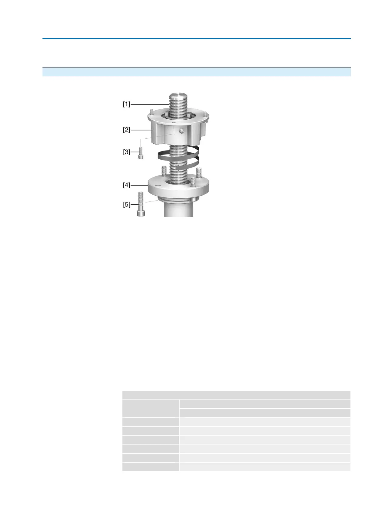
Figure 12: Assembly of output drive type A
[1] Valve stem
[2] Output drive type A
[3] Screws to actuator
[4] Valve flange
[5] Screws to output drive
Procedure
1. If output drive type A is already mounted to the multi-turn actuator: Loosen
screws [3] and remove output drive type A [2].
2. Apply a small quantity of grease to the valve stem [1].
3. Place output drive type A on valve stem and turn until it is flush on the valve
flange.
4. Turn output drive type A until alignment of the fixing holes.
5. Screw in fastening screws [5], however do not completely tighten.
6. Fit multi-turn actuator on the valve stem so that the stem nut dogs engage into
the output drive sleeve.
➥
The flanges are flush with each other if properly engaged.
7. Adjust multi-turn actuator until alignment of the fixing holes.
8. Fasten multi-turn actuator with screws [3].
9. Fasten screws [3] crosswise with a torque according to table.
Table 11:
Tightening torques for screws
Tightening torque [Nm]Threads
Strength class A2-80/A4–80
10M6
24M8
48M10
82M12
200M16
392M20
10. Turn multi-turn actuator with handwheel in direction OPEN until valve flange
and output drive type A are firmly placed together.
19
SA 07.2 – SA 16.2 / SAR 07.2 – SAR 16.2 Control unit: electronic (MWG)
AC 01.2 Non-Intrusive EtherNet/IP Assembly