11. Tighten fastening screws [5] between valve and output drive type A crosswise
applying a torque according to table.
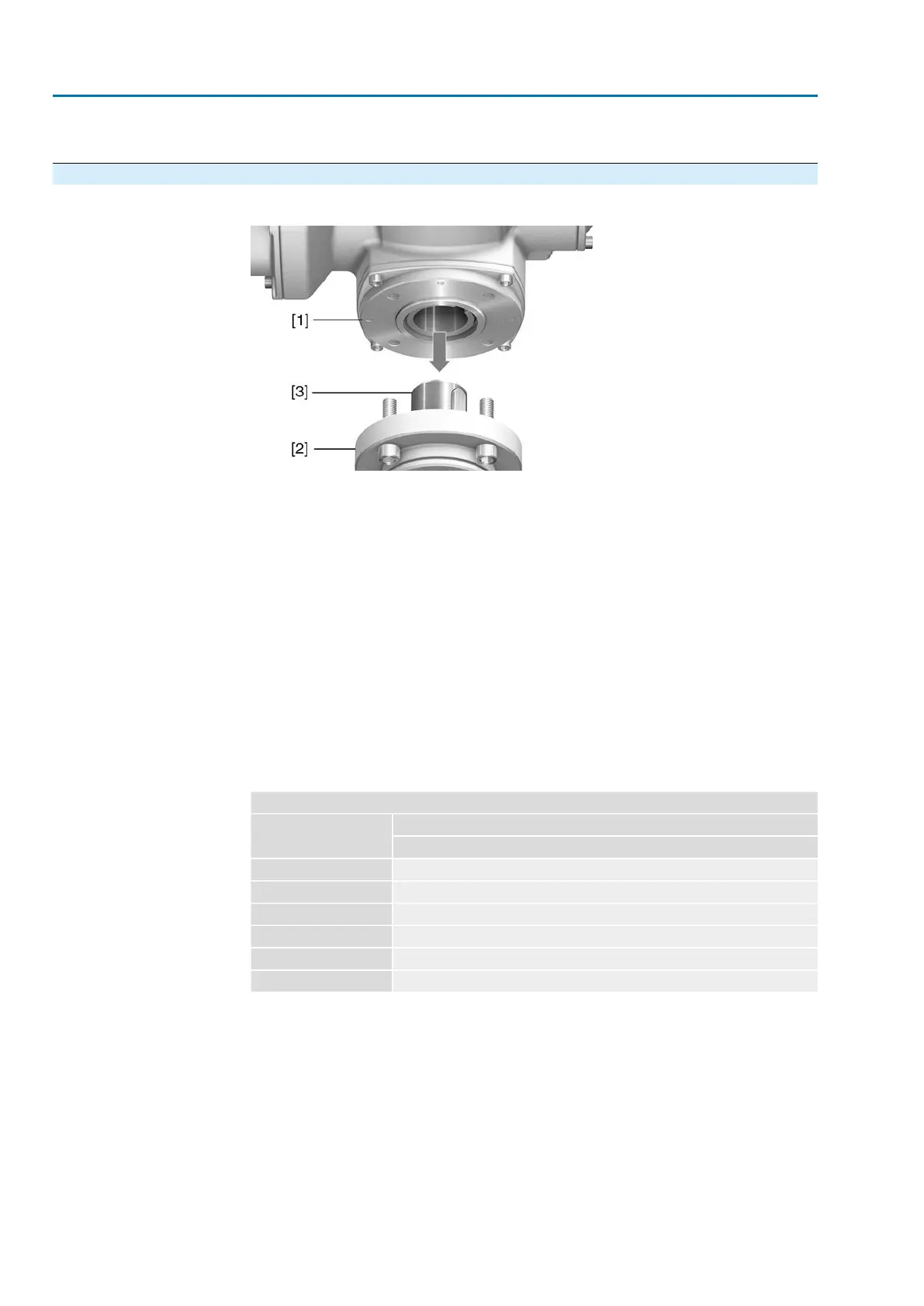
4.4.3. Multi-turn actuator with output drive type B: mount
Figure 13: Mounting output drive types B
[1] Multi-turn actuator
[2] Valve/gearbox
[3] Valve/gearbox shaft
Procedure
1. Check if mounting flanges fit together.
2. Check if output drive of multi-turn actuator [1] matches the output drive of
valve/gearbox or valve/gearbox valve shaft [2/3].
3. Apply a small quantity of grease to the valve or gearbox shaft [3].
4. Place multi-turn actuator [1] and ensure that the spigot fits uniformly in the recess
and that the mounting faces are in complete contact.
5. Fasten multi-turn actuator with screws according to table.
Information: We recommend applying liquid thread sealing material to the
screws to avoid contact corrosion.
6. Fasten screws crosswise to a torque according to table.
Table 12:
Tightening torques for screws
Tightening torque [Nm]Threads
Strength class A2-80/A4–80
10M6
24M8
48M10
82M12
200M16
392M20
20
SA 07.2 – SA 16.2 / SAR 07.2 – SAR 16.2 Control unit: electronic (MWG)
Assembly AC 01.2 Non-Intrusive EtherNet/IP