7.3. Indication lights of local controls
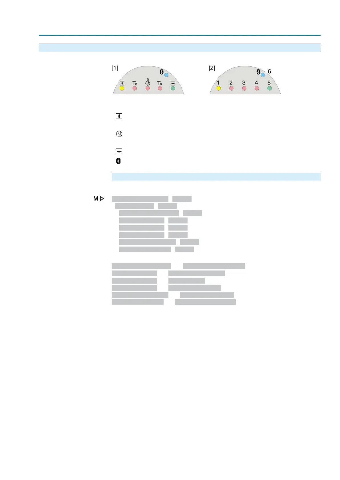
Figure 64: Arrangement and signification of indication lights
[1] Marking with symbols (standard)
[2] Marking with figures 1 – 6 (option)
1
End position CLOSED reached (blinking: operation in direction CLOSE)
2 Tc Torque fault CLOSE
3
Motor protection tripped
4 To Torque fault OPEN
5
End position OPEN reached (blinking: operation in direction OPEN)
6
Bluetooth connection
Modify indication light assignment (indications)
Different indications can be assigned to LEDs 1 – 5.
Device configuration M0053
Local controls M0159
Indication light 1 (left) M0093
Indication light 2 M0094
Indication light 3 M0095
Indication light 4 M0096
Indicat. light 5 (right) M0097
Signal interm. pos. M0167
Defaut values (Europe):
Indication light 1 (left) = End p. CLOSED, blink
Indication light 2 = Torque fault CLOSE
Indication light 3 = Thermal fault
Indication light 4 = Torque fault OPEN
Indicat. light 5 (right) = End p. OPEN, blink
Signal interm. pos. = OPEN/CLOSED = Off
Further setting values:
Refer to Manual (Operation and setting).
53
SA 07.2 – SA 16.2 / SAR 07.2 – SAR 16.2 Control unit: electronic (MWG)
AC 01.2 Non-Intrusive EtherNet/IP Indications