5.4.1. Terminal compartment (for mains connection): open
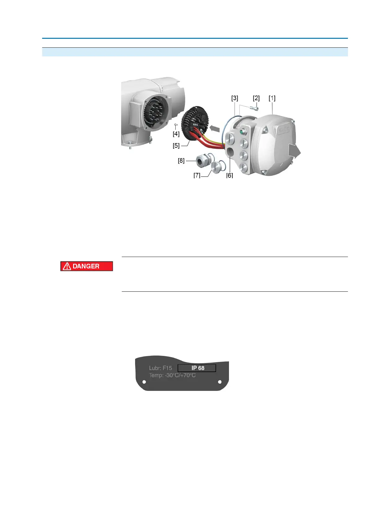
Figure 28: Open mains terminal compartment
[1] Connection housing
[2] Screws for frame
[3] O-ring
[4] Screws for socket carrier
[5] Socket carrier
[6] Cable entries for mains connection (pins for motors and pins for controls)
[7] Blanking plug
[8] Cable gland (not included in scope of delivery)
Electric shock due to presence of hazardous voltage!
Failure to observe this warning results in death or serious injury.
→
Disconnect device from the mains before opening.
1. Loosen screws [2] and remove connection housing [1].
2. Loosen screws [4] and remove socket carrier [5] from connection housing [1].
3. Insert cable glands [8] suitable for connecting cables.
➥
The enclosure protection IP… stated on the name plate is only ensured if suit-
able cable glands are used.
Figure 29: Example: Name plate for enclosure protection IP68
4. Seal unused cable entries [6] with suitable blanking plugs [7].
Information
Fieldbus connection can be accessed separately from the mains connection (refer
to <Fieldbus terminal compartment: open>.
33
SA 07.2 – SA 16.2 / SAR 07.2 – SAR 16.2 Control unit: electronic (MWG)
AC 01.2 Non-Intrusive EtherNet/IP Electrical connection