29
During Safe ESD operation, the actuator has to stop when reaching the position set via limit
switching. Safe ESD operation must also be stopped if the tripping torque set via the MWG.2
is exceeded.
1. Operate actuator in mid-position or at sufficient distance from the end positions.
2. Execute operation command in opposite direction of the configured Safe ESD
safety function:
- For “Safe CLOSING” (Safe ESD in direction CLOSE) configuration: Start
operation command in direction OPEN.
- For ““Safe OPENING” (Safe ESD in direction OPEN) configuration: Start
operation command in direction CLOSE.
Information: For the test, operation commands (in directions OPEN or CLOSE) can
be executed both from remote (via DCS) and from Local at the controls (via the
push buttons of the local controls).
3. Start safety operation during operation:
- Set Safe ESDa and Safe ESDb input signals to 0 V (low).
® Safety function is correct if the actuator stops and performs a safety operation into
the configured direction.
® No SIL fault signal may be issued.
4. Set Safe ESDa and Safe ESDb input signals to +24 V DC (high) after the test.
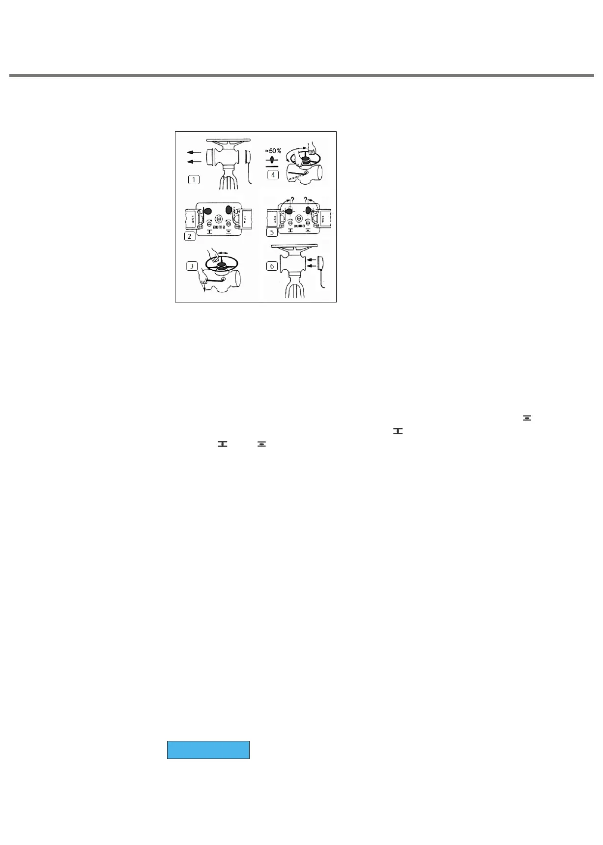
1.
Remove cover at switch compartment (fig.1)
2.
Check whether limit-switch has tripped (fig.2)Valve completely closed : WSR tripped
Valve completely opened : WOL tripped
3.
Engage manual drive :
Push declutch lever as indicated by arrow (fig. 3). If resistance is felt, turn handwheel
slowly while lever is pressed till manual drive engages.
4.
Operate valve to intermediate position manually (fig.4) Direction OPEN ( ) turn
handwheel anti-clockwise. Direction CLOSED ( ) turn handwheel clockwise. Switch
cam at (Z) or (O) should rotate 90°and release the switch (fig. 5) if set properly.
Initiate safety operation
:
Set Safe ESDa and Safe ESDb input signals to 0 V (low).
5.
Ensure sealing faces at control plug are clean and check whether O-ring is ok. Apply
thin film of non - acid grease to sealing faces and then replace plug cover (fig. 6).
Check seating via limit switches
6. Operate limit switches until test is complete:
® For “Safe CLOSING” (Safe ESD in direction CLOSE) configuration: Activate
SIL ESDa/ ESDb command until close limit switch trips, then validate the
valve position on EPAC display as 0.00%.
® For "Safe OPENING” (Safe ESD in direction OPEN) configuration: Activate
SIL ESDa/ ESDb command until Open limit switch trips, then validate the
valve position on EPAC display as 100%
ü
The safety function reaction to the limit switch signals is correct if safety operation
is stopped.
7. After limit switching evaluation:
· Set Safe ESDa and Safe ESDb input signals to +24 V DC (high).
· Operate actuator via local controls or from REMOTE to end position
OPEN and then to end position CLOSED.
· Operate actuator to mid-position or at sufficient distance from the
end positions.
þ
Thermo switches are provided to protect Motor windings.
þ
Be connected in panel control circuit (Refer Terminal Plan), else our warranty is void
NOTICE
10. Start actuator in CLOSED direction and switch off by manually tripping torque switch
DSR. Trip switch by operating lever easily only! (fig.10). For actuators with double
torque switch, check OPEN direction in the same way.
11. For position seated closing: Start actuator in CLOSED direction and switch off by
manually tripping limit switch WSR (fig.11)
12. If actuator does not stop, check connection of terminals and the control wiring.
13. Determine over-run of actuator in both directions by visual inspection (amount of
additional rotation of spindle or valve movement after actuator is switched off).
14. Engage manual drive and operate actuator to fully closed position (fig. 12), while
observing the switch cam for limit switch WSR.
For position seating: When the switch has tripped (fig. 13) continue turning handwheel
to the final position and check whether the remaining travel corresponds to the over-
run. If not, reset to suit. See point 14.
For torque seating: Limit switch WSR must trip shortly before reaching end-position
CLOSED (fig. 13).
15. Operate actuator manually to OPEN-position (fig. 14). Check in the same way as
described above for position seating, see point 12 (fig. 15).
16. Resetting limit-switching:
- Operate valve away from end-position to account for over-run or to the desired
switch tripping point.
- Push thrust bolt I inwards and turn (fig. 16). The bolt remains in this position.
- For CLOSED position turn spindle marked (Z), (for OPEN position spindle
marked, (O) slowly as indicated by arrow (fig. 16). Distinct "clicks" can be felt
and heard. Continue turning the spindle until the cam operates the switch. At this
stage, the spindle should not "click" any more and should not be turned any further.
If inadvertently you override the tripping point, continue turning the spindle slowly
in the same direction till the switch cam goes back to its original position. Repeat
setting instructions as above described.
- Turn thrust bolt I till it snaps back into its original position by spring action.
17. Torque switching (fig. 17)
If the actuator is switched off by torque switch over its travel before reaching an end-
position, please check whether the valve stem is damaged or dirt adhering to it. If
necessary, and with the valve maker's consent, the setting of the tripping torque may
be raised slightly.
18. Setting: Figures on the torque switch operating cam indicate the valves in Nm (1 mkp
= 10 Nm. 1 lbsft. = 1.36 Nm).
Loosen screw and turn the cam till the desired torque coincides with the arrow mark,
then fasten lock-screw.
19. Immediately after start-up: Ensure sealing faces at cover and housing are clean. Check
whether O-ring is correctly in position and apply a thin film of non-acid grease. Replace
the cover and fasten with 4 screws (fig. 18)
#
Multi-turn actuators
SA series with Control 3.XX /NI/SIL