13
4 Safety instrumented systems and safety functions
4.1 Safety instrumented system including an actuator
Typically, a safety instrumented system including an actuator is composed of the
components as shown in the figure.
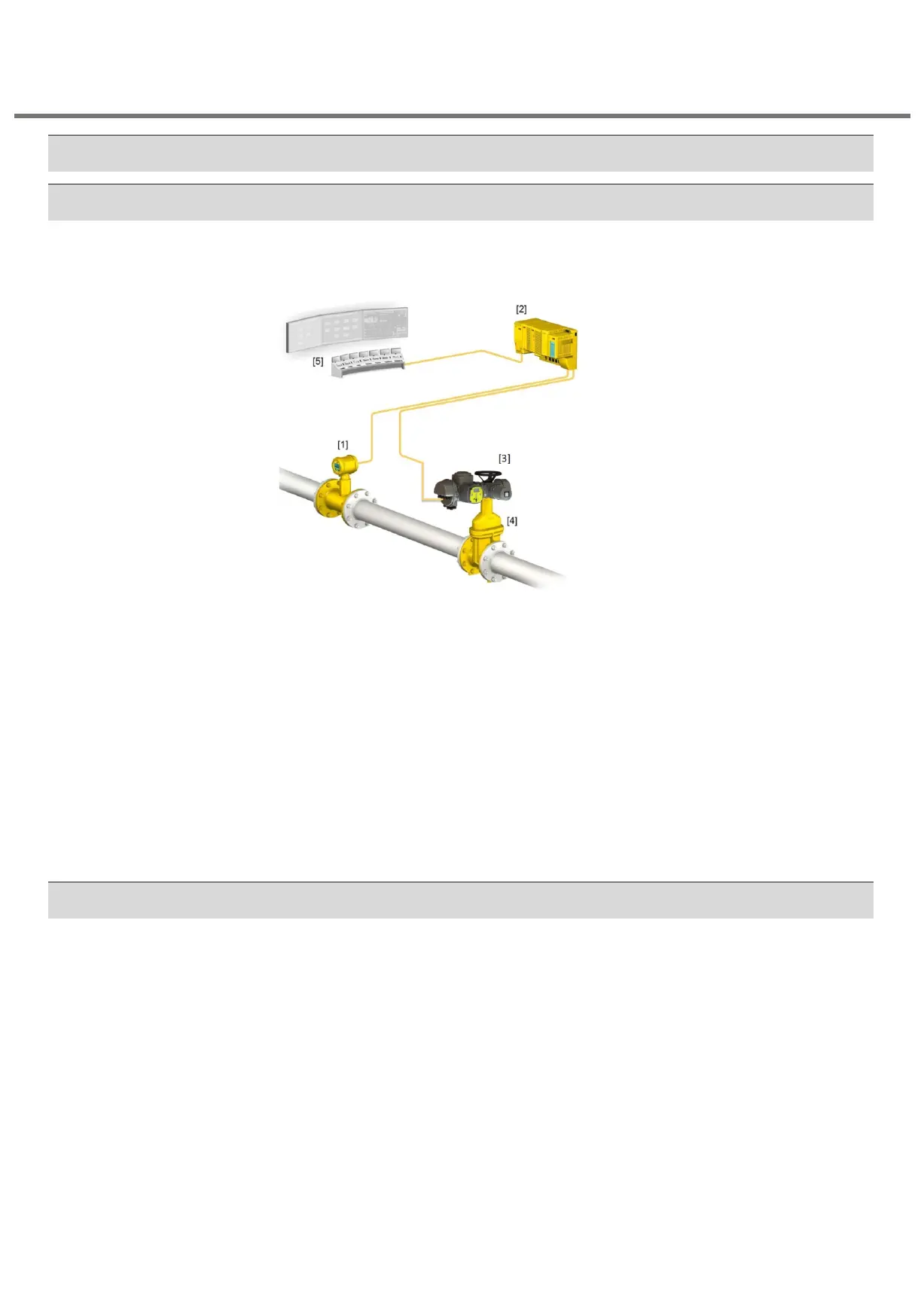
Figure 2: Typical safety instrumented system
[1] Sensors
[2] Controls (safety PLC)
[3] Actuator with actuator controls
[4] Valve
[5] Process control system
The safety integrity level is always assigned to an overall safety instrumented system and not
to an individual component.
For an individual component (e.g. an actuator), safety figures are determined. These figures
are used to assign the devices to a potential safety integrity level (SIL). The final classification
of the safety instrumented system can only be made after assessing and calculating all
subsystems.
In calculating the safety figures of actuators, the following safety functions are taken into
account:
• Safe ESD function (Emergency Shut Down): Safe OPENING/CLOSING
- Redundant Safe ESDa and Safe ESDb signals (standard: low active) make the
actuator travel to the configured direction (OPEN/CLOSE).
• Safe STOP function: Safe STOP
- An operation command of standard controls (in directions OPEN or CLOSE) will only
be executed if an additional enable signal for the operation command is applied.
- If this is not the case, operation in directions OPEN or CLOSE is stopped or even
suspended (motor is switched off).
• Safe ESD function combined with Safe STOP function.
- Safe ESD function has a higher priority i.e. if both functions are activated, the
actuator is operated into the configured direction (OPEN/CLOSE).
Multi-turn actuators
SA series with Control 3.XX /NI/SIL