Home
AUMA
Controller
SAR 07.2
AUMA SAR 07.2 Operation Instructions
4
of 1
of 1 rating
100 pages
Give review
Manual
Specs
To Next Page
To Next Page
To Previous Page
To Previous Page
Loading...
15.
Certificates
Information
Cer
tificates are valid as from the indicated date of issue
.
Subject to changes without
notice.
The latest v
ersions are attached to the device upon deliv
er
y and also a
vailab
le
f
or download at http://www
.auma.com.
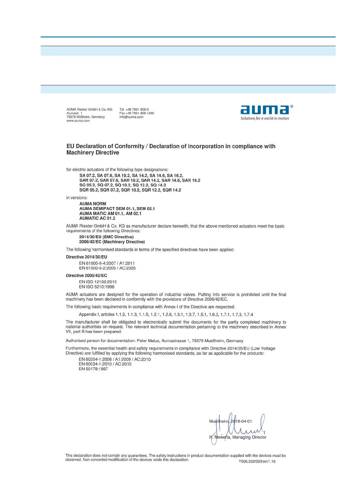
15.1.
Declaration of Incorporation and EU Dec
laration of Conformity
91
SA 07.2
–
SA 16.2/SAR 07.2
–
SAR 16.2 Control unit:
electronic (MWG)
A
C 01.2 Non-Intr
usiv
e HAR
T
Cer
tificates
90
92
Table of Contents
Default Chapter
2
Table of Contents
2
1 Safety Instructions
5
Basic Information on Safety
5
Range of Application
5
Applications in Ex Zone 22 (Option)
6
Warnings and Notes
6
References and Symbols
7
2 Identification
8
Name Plate
8
Short Description
11
3 Transport, Storage and Packaging
12
Transport
12
Storage
14
Packaging
14
4 Assembly
15
Mounting Position
15
Handwheel Fitting
15
Multi-Turn Actuator: Mount to Valve/Gearbox
15
Output Drive Type a
15
4.3.1.1. Stem Nut: Finish Machining
16
4.3.1.2. Multi-Turn Actuator (with Output Drive Type A): Mount to Valve
17
Output Drive Types B
18
4.3.2.1. Multi-Turn Actuator with Output Drive Types B: Mount to Valve/Gearbox
19
Accessories for Assembly
20
Stem Protection Tube for Rising Valve Stem
20
Mounting Positions of Local Controls
21
Mounting Positions: Modify
21
5 Electrical Connection
22
Basic Information
22
S/SH/SD Electrical Connection (AUMA Plug/Socket Connector)
24
Terminal Compartment (for Mains Connection): Open
26
Cable Connection
27
Terminal Compartment (for Mains Connection): Close
29
HART Terminal Compartment: Open (Version with HART Connection Board)
30
HART Cables: Connect
31
HART Terminal Compartment: Close (Version with HART Connection Board)
33
Accessories for Electrical Connection
34
Controls Mounted on Wall Bracket
34
Parking Frame
35
DS Intermediate Frame for Double Sealing
35
External Earth Connection
36
Operation
37
Manual Operation
37
Engage Manual Operation
37
Manual Operation: Disengage
37
Motor Operation
38
Local Actuator Operation
38
Actuator Operation from Remote
39
Menu Navigation Via Push Buttons (for Settings and Indications)
39
Menu Layout and Navigation
40
User Level, Password
41
Password Entry
41
Password Change
42
Language in the Display
42
Language Change
43
Indications
44
Indications During Commissioning
44
Indications in the Display
44
Feedback Indications from Actuator and Valve
45
Status Indications According to AUMA Classification
48
Status Indications According to NAMUR Recommendation
48
Indication Lights of Local Controls
50
Optional Indications
51
Mechanical Position Indication (Self-Adjusting)
51
Mechanical Position Indication Via Indicator Mark
51
Signals (Output Signals)
52
Signals Via HART
52
Status Signals Via Output Contacts (Digital Outputs)
52
Assignment of Outputs
52
Coding the Outputs
52
Analogue Signals (Analogue Outputs)
52
Commissioning (Basic Settings)
53
Type of Seating: Set
53
Torque Switching: Set
54
Limit Switching: Set
55
HART Address (Slave Address): Set
57
Test Run
58
Direction of Rotation at Mechanical Position Indicator: Check
58
Direction of Rotation at Hollow Shaft/Stem: Check
59
Limit Switching: Check
60
Commissioning (Settings/Options in the Actuator)
61
Switch Compartment: Open/Close
61
Mechanical Position Indicator (Self-Adjusting)
62
Mechanical Position Indicator: Set
62
Gear Stage of the Reduction Gearing: Test/Set
63
Mechanical Position Indication Via Indicator Mark (Not Self-Adjusting)
64
Mechanical Position Indicator: Set
64
Gear Stage of the Reduction Gearing: Test/Set
64
Corrective Action
67
Faults During Commissioning
67
Fault Indications and Warning Indications
67
Fuses
71
Fuses Within the Actuator Controls
71
Motor Protection (Thermal Monitoring)
73
Servicing and Maintenance
74
Preventive Measures for Servicing and Safe Operation
74
Maintenance
74
Disposal and Recycling
75
Technical Data
76
Technical Data Multi-Turn Actuators
76
Technical Data Actuator Controls
78
Spare Parts
85
Multi-Turn Actuators SA
85
Sa 16.2/Sar 07.2
85
AC 01.2 Actuator Controls
87
Actuator Controls AC 01.2 - Fieldbus
89
Certificates
91
Declaration of Incorporation and EU Declaration of Conformity
91
Index
94
Addresses
97
Other manuals for AUMA SAR 07.2
Operation Manual
108 pages
Operating Instructions
104 pages
Manual
52 pages
Assembly Instructions
3 pages
4
Based on 1 rating
Ask a question
Give review
Questions and Answers:
Need help?
Do you have a question about the AUMA SAR 07.2 and is the answer not in the manual?
Ask a question
AUMA SAR 07.2 Specifications
General
Type of actuator
Multi-turn actuator
Protection class
IP68
Output speed
4 to 180 rpm
Ambient temperature
-25°C to +70°C
Housing material
Aluminum
Related product manuals
AUMA SAR 07.6
104 pages
AUMA SAR 07.5
80 pages
AUMA SAR 07.1 - SAR 30.1
60 pages
AUMA SAR 6
44 pages
AUMA SAR 12
44 pages
AUMA SAR 10.2
104 pages
AUMA SAR 14.6
104 pages
AUMA SAR 14.1
80 pages
AUMA SAR 14.5
80 pages
AUMA SAR 10.1
80 pages
AUMA SAR 16.2
108 pages
AUMA SA 48.1 SAR 25.1
92 pages