ZoneLogix™ PRO Zone Controller User Guide | Revision 1.0 November 2019 | Page 11
2.2
Zone Installation
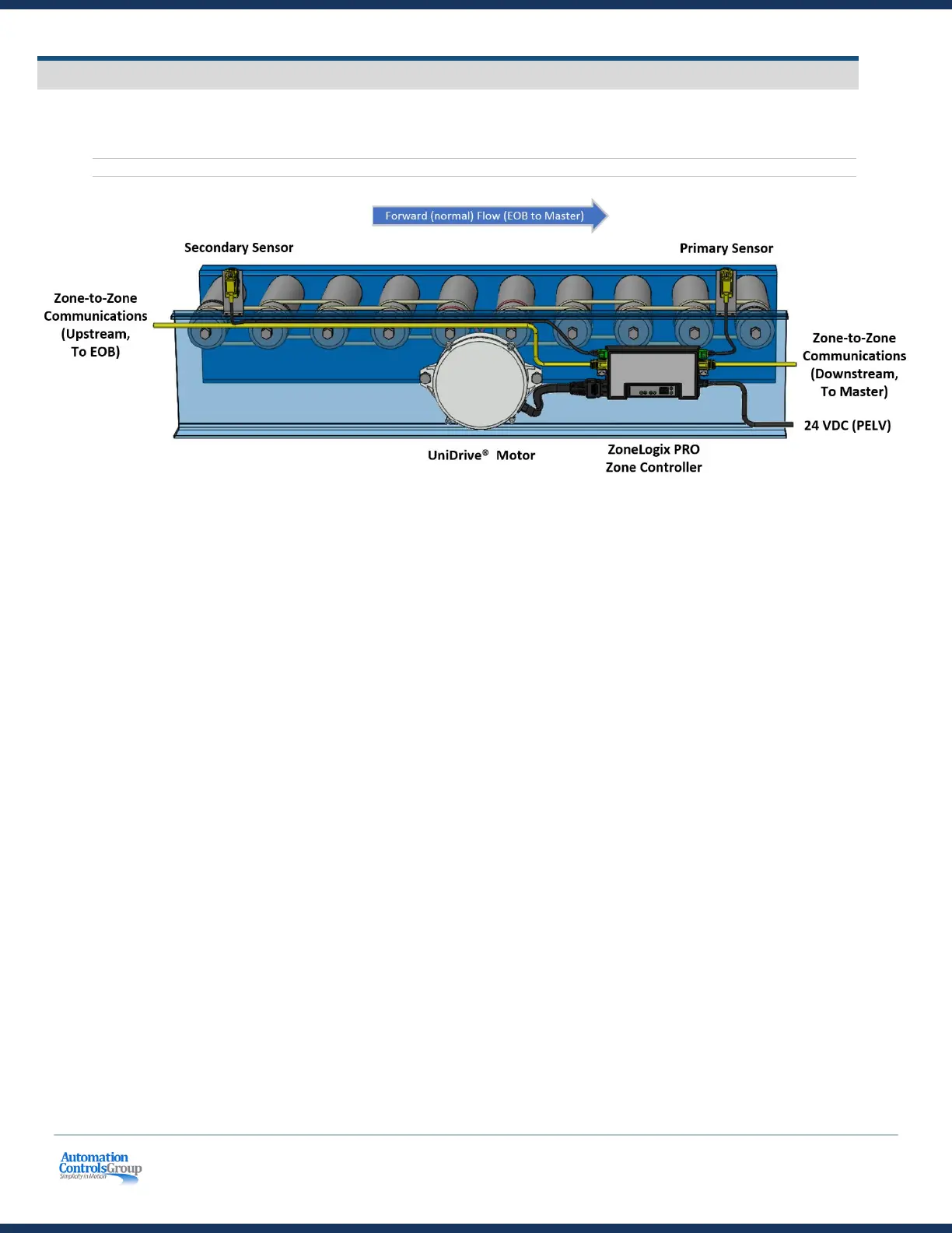
A typical zone is installed as shown below.
Figure 4: The ZoneLogix™ PRO System
• The motor is typically placed in the middle of the zone
• The Primary Sensor is used as the zone photoeye sensor input when package flow is left to right (Forward
Direction EOB to Master)
• The Secondary Sensor is used as the zone photoeye sensor input when package flow is right to left (Reverse
Direction Master to EOB)
• The photoeye sensor should be a 24 VDC PNP, where the output is 24 VDC when a package is detected
• The recommended photoeye sensor placement is typically ~6” at <30 m/min, with respect to the
downstream edge of the zone. The sensor position is determined by factors such as the speed and weight of
the object. Heavier loads at higher speeds require greater distance to stop moving.
• Maximum load current of the photoeye sensor should be <150 mA
• Mount the control where there is adequate heatsink and no strain on the cable connections
 Loading...