ZoneLogix™ PRO Zone Controller User Guide | Revision 1.0 November 2019 | Page 14
2.4
+24VDC Power Connection
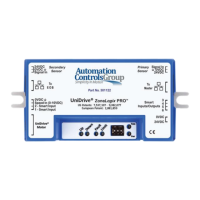
CAUTION! Power must be applied with proper polarity to avoid potentially damaging the Zone Controller. Follow the pinout shown
in Table 1 below.
The ZoneLogix™ PRO operates from +22 to +28 volts DC power. Make the power connection only after all other
connections have been made.
Table 1: DC Power Input Connection
IMPORTANT! When adjacent zones are operating from separate power supplies, connect their DC grounds. However, do not
connect their positive voltage pins together. The positive voltage differential should be < 4 VDC.
2.5
Zone-to-Zone Cable Connection
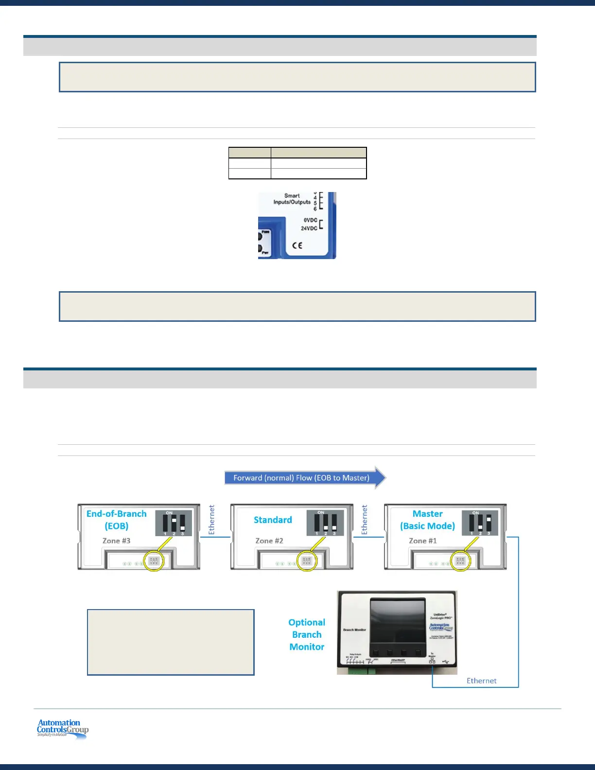
The controls pass Branch Serial Communications and Handshaking signals between adjacent zones over standard
Ethernet cables. The To EOB connector must be connected to the To Master connector of an adjacent upstream unit.
The To Master connector must be connected to an adjacent downstream unit using its To EOB connector. When
connecting two branches together, see Section 7: Breakout Module.
Figure 7: Zone-to-Zone Communication Connections
CAUTION! Do not cross wiring of the
Ethernet cables. The left side of the zone
must connect to the adjacent zone on the
left, and the right side of the zone must
connect to the adjacent zone on the right.
Zones should be connected as shown above.
 Loading...