ZoneLogix™ PRO Zone Controller User Guide | Revision 1.0 November 2019 | Page 10
This section describes how to install the ZoneLogix™ PRO and UniDrive
®
motors in the most common
configuration.
2.1
Zone Controller Installation
Mount the Zone Controller in a location where the motor cable reaches the connection header without putting strain
on the cable connector or the header. The Zone Controller can mount to the conveyor frame using two ¼ inch (0.25
in or 6.35 mm) bolts.
CAUTION: If mounting the control on a curved section of conveyor, use washers between the mounting plate and the conveyor
frame. This is to assure that the mounting plate is not distorted, causing damage to the enclosed printed circuit board assembly.
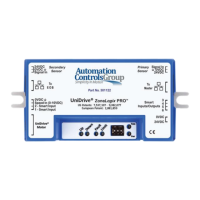
Figure 3: Zone Controller Mounting Tabs
CAUTION: Removal of the cover will void the warranty. The cover does not make the controller waterproof or dustproof.
 Loading...