ZoneLogix™ PRO Zone Controller User Guide | Revision 1.0 November 2019 | Page 8
2
Getting Started and Installation
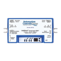
Below is an image of the Zone Controller and the various connections. In Basic Mode there are a few
operational mode settings that can be made via Smart I/O settings which are described later in this
manual. To configure a system in Advanced Mode, see Section 5: Advanced Mode System
Configuration.
Figure 2: ZoneLogix™ PRO Zone Controller Diagram
1) Secondary Sensor: Photoeye input for the downstream edge of a zone, when configured for the
Reverse flow direction.
a. Phoenix Contact, 3-pos plug, 1881338
2) To EOB Communication: This is meant to only connect to the “To Master” connection of
another Zone Controller. Zone Controllers are intended to be daisy chained together in a series.
a. RJ45, 8P8C, CAT5 (or better), Ethernet cable
 Loading...